-150-
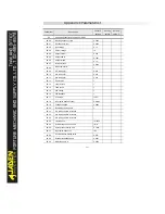
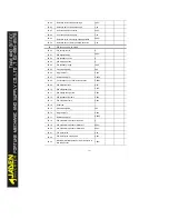
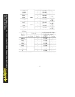
P9.23
Power-on time upon 3rd fault
-
P9.24
Running time upon 3rd fault
-
P9.27
Frequency upon 2nd fault
-
P9.28
Current upon 2nd fault
-
P9.29
Bus voltage upon 2nd fault
-
P9.30
DI status upon 2nd fault
-
P9.31
Output terminal status upon 2nd fault
-
P9.32
2nd faultinverter status
-
P9.33
Power-on time upon 2nd fault
-
P9.34
Running time upon 2nd fault
-
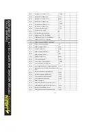
P9.37
Frequency upon 1st fault
-
P9.38
Current upon 1st fault
-
P9.39
Bus voltage upon 1st fault
-
P9.40
DI status upon 1st fault
-
P9.41
Output terminal status upon 1st fault
-
P9.42
1st faultinverter status
-
P9.43
Power-on time upon 1st fault
-
P9.44
Running time upon 1st fault
-
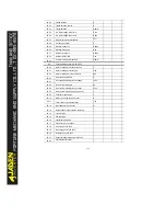
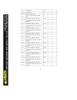
P9.47
Fault protection action selection 1
00000
P9.48
Fault protection action selection 2
00000
P9.49
Fault protection action selection 3
00000
P9.50
Fault protection action selection 4
00000
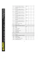
P9.54
Frequency selection for continuing to run upon
fault
0
P9.55
Backup frequency upon abnormality
100.0%
P9.56
Type of motor temperature sensor
0
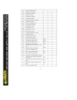
P9.57
Motor overheat protection threshold
110
℃
P9.58
Motor overheat warning threshold
90
℃
P9.59
Action selection at instantaneous power failure
P9.60
Action pause judging voltage at instantaneous
power failure
90.0%
P9.61
Voltage rally judging time at instantaneous power
failure
0.50s
P9.62
Action judging voltage at instantaneous power
failure
80.0%
P9.63
Protection upon load becoming 0
0
Summary of Contents for DLB1-0D40S2G
Page 11: ...11 Graph 1 722 30KW product outline dimensions Graph 1 837 55KW product outline dimensions...
Page 12: ...12 Graph 1 875 110KW product outline dimensions Graph 1 9 132 160KW product outline dimensions...
Page 14: ...14 2 Wirings 2 1 Standard wiring diagrams Graph 2 8 0 4 18 5KW inverter wiring diagram...
Page 15: ...15 Graph 2 922 400KW inverter wiring diagram...
Page 159: ...159...

