-151-
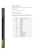
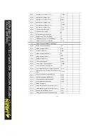
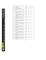
P9.64
Detection level of load becoming 0
10.0%
P9.65
Detection time of load becoming 0
1.0s
P9.67
Over-speed detection value
20.0%
P9.68
Over-speed detection time
1.0s
P9.69
Detection value of too large speed deviation
20.0%
P9.70
Detection time of too large speed deviation
5.0s
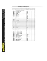
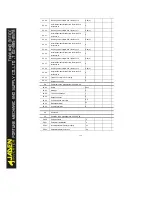
PA
PID functions:PA.00-PA.28
PA.00
PID setting source
0
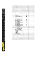
PA.01
PID digital setting
50.0%
PA.02
PID feedback source
0
PA.03
PID action direction
0
PA.04
PID feedback range
1000
PA.05
Proportional gainK
p1
20.0
PA.06
Integral timeTi
1
2.00s
PA.07
Differential timeTd
1
0.000s
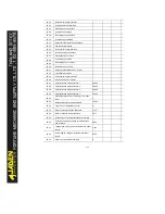
PA.08
Cut-off frequency of PID reverse rotation
2.00Hz
PA.09
PID deviation limit
0.0%
PA.10
PID differential limit
0.10%
PA.11
PID setting change time
0.00s
PA.12
PID feedback filter time
0.00s
PA.13
PID output filter time
0.00s
PA.14
Reserved
-
PA.15
Proportional gainK
p2
20.0
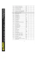
PA.16
Integral timeTi
2
2.00s
PA.17
Differential timeTd
2
0.000s
PA.18
PID parameter switchover condition
0
PA.19
PID parameter switchover deviation 1
20.0%
PA.20
PID parameter switchover deviation 2
80.0%
PA.21
PID initial value
0.0%
PA.22
PID initial value holding time
0.00s
PA.23
Maximum deviation between two PID outputs in
forward direction
1.00%
Summary of Contents for DLB1-0D40S2G
Page 11: ...11 Graph 1 722 30KW product outline dimensions Graph 1 837 55KW product outline dimensions...
Page 12: ...12 Graph 1 875 110KW product outline dimensions Graph 1 9 132 160KW product outline dimensions...
Page 14: ...14 2 Wirings 2 1 Standard wiring diagrams Graph 2 8 0 4 18 5KW inverter wiring diagram...
Page 15: ...15 Graph 2 922 400KW inverter wiring diagram...
Page 159: ...159...

