-168-
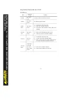
Using Peripheral Electrical Devices for DLB1
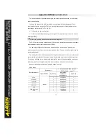
See table below:
Name
Installation
position
Functions
Air switch
Before input
cicuit
Cut-off current when the device is over-current
Contactor
Input side of
inverter
On-off power supply for inverters.
Input AC
reactor
Input side of
inverter
1
)
Increase power factor of input side;
2
)
Reduce input side higher harmonics;
3
)
Eliminate input current imbalance caused by power phase
imbalance.
Input EMC
filter
Input side of
inverter
1
)
Reduce inverter EMI transmission and emission;
2
)
Improve inverter counter interference capability.
DC reactor
DC bus of
inverter
1
)
Increase power factor of input side;
2
)
Increase inverter efficiency&thermal stability;
3
)
Reduce negative effects from input side higher harmonics
and reduce inverter EMI transmission and emission.
Output AC
reactor
Output side of
inverter and
input side of
motor, close to
inverter
1
)
Protect motors from higher harmonics;
2
)
Reduce effects of leakage current to motors.
Summary of Contents for DLB1-0D40S2G
Page 11: ...11 Graph 1 722 30KW product outline dimensions Graph 1 837 55KW product outline dimensions...
Page 12: ...12 Graph 1 875 110KW product outline dimensions Graph 1 9 132 160KW product outline dimensions...
Page 14: ...14 2 Wirings 2 1 Standard wiring diagrams Graph 2 8 0 4 18 5KW inverter wiring diagram...
Page 15: ...15 Graph 2 922 400KW inverter wiring diagram...
Page 159: ...159...

