-31-
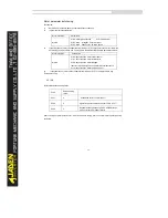
4.2 Basic functions group:P0.00-P0.28
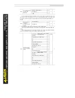
Code
Description
Setting range
Defa
ult
Restri
ctions
P0.00
Load type
G type
1
-
●
P type
2
This parameter is used to display the delivered model and cannot be modified.
1: Applicable to constant torque load with rated parameters specified
2: Applicable to variable torque load (fan and pump) with rated parameters specified.
P0.01
Speed control mode
Sensorless flux vector control (SVC)
0
2
★
Closed-loop vector control (FVC)
1
V/F control
2
It indicates open-loop vector control, and is applicable to high-performance control applications such as
machine tool, centrifuge, wire drawing machine and injection molding machine. One Invertercan operate
only one motor.
1: Closed-loop vector control (FVC)
It is applicable to high-accuracy speed control or torque control applications such as high-speed paper
making machine, crane and elevator. One Invertercan operate only one motor. An encoder must be
installed at the motor side, and a PG card matching the encoder must be installed at the Inverterside.
2: Voltage/Frequency (V/F) control
It is applicable to applications with low load requirements or applications where one Inverteroperates
multiple motors, such as fan and pump.
Notes:
If vector control is used, motor auto-tuning must be performed because the advantages of vector control
can only be utilized after correct motor parameters are obtained. Better performance can be achieved by
adjusting speed regulator parameters in group P2.
For the permanent magnetic synchronous motor (PMSM), the DLB1 does not support SVC. FVC is used
generally. In some low-power motor applications, you can also use V/F.
DLB2 supports SVC control of PMSM.
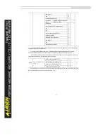
P0.02
Command source
channel
Operation panel command channel (LED
OFF)
0
0
☆
Terminalcommand channel (LED ON)
1
Communicationcommand channel
(LEDblinks)
2
It is used to determine the input channel of the Invertercontrol commands, such as run, stop, forward
rotation, reverse rotation and jog operation. You can input the commands in the following three channels:
0: Operation panel control ("LOCAL" indicator off)
Commands are given by pressing keys on the operation panel.
1: Terminal control ("LOCAL" indicator on)
Summary of Contents for DLB1-0D40S2G
Page 11: ...11 Graph 1 722 30KW product outline dimensions Graph 1 837 55KW product outline dimensions...
Page 12: ...12 Graph 1 875 110KW product outline dimensions Graph 1 9 132 160KW product outline dimensions...
Page 14: ...14 2 Wirings 2 1 Standard wiring diagrams Graph 2 8 0 4 18 5KW inverter wiring diagram...
Page 15: ...15 Graph 2 922 400KW inverter wiring diagram...
Page 159: ...159...


