-33-
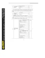
3: AI2 (0-10 V voltage input or 4-20 mA current input, determined by jumper J8)
The frequency is set by analog input. The DLB1 control board provides two analog input (AI)
terminals (AI1, AI2).
The DLB1 provides three curves indicating the mapping relationship between the input voltage of
AI1& AI2 and the target frequency. You can set the curves by using function code group P4. When AI is
used as the frequency setting source, the corresponding value 100% of the voltage/current input
corresponds to the value of P0.10 (Maximum frequency).
4:AI3(keyboard potentiometer)
5: Pulse setting (DI5)
The frequency is set by DI5 (high-speed pulse). The signal specification of pulse setting is 9-30 V
(voltage range) and 0-100 kHz (frequency range). The corresponding value 100% of pulse setting
corresponds to the value of P0.10 (Maximum frequency).
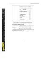
6:Multi-speed operation setting
In multi-speed operation setting mode, combinations of different DI terminal states correspond to
different set frequencies. The DLB1 supports maximum 16 speeds implemented by 16 state
combinations of four DI terminals in Group PC. The multi-speed operation settingindicates percentages
of the value of P0.10 (Maximum frequency).
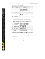
If a DI terminal is used for the multi-speed operation setting, you need to set in group P4.
7: Simple PLC setting
When the simple programmable logic controller (PLC) mode is used as the frequency source, the
running frequency of the invertercan be switched over among the 16 frequency references. You can set
the holding time and acceleration/deceleration time of the 16 frequency references. For details, refer to
the descriptions of Group PC.
8:PID control setting
The output of PID control is used as the running frequency. PID control is generally used in on-site
closed-loop control, such as constant pressure closed-loop control and constant tension closed-loop
control.
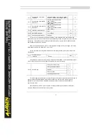
When applying PID as the frequency source, you need to set in group PA.
9:Remote communication setting
The frequency is set by means of communication.
The DLB1 supports four host computer communication protocols: Modbus, PROFIBUS-DP,
CANopen and CANlink. They cannot be used simultaneously.
If the communication mode is used, a communication card must be installed. The DLB1 provides
four optional communication cards and you can select one based on actual requirements. The
corresponding serial communication protocol needs to be selected based on the setting of P0.28.
Summary of Contents for DLB1-0D40S2G
Page 11: ...11 Graph 1 722 30KW product outline dimensions Graph 1 837 55KW product outline dimensions...
Page 12: ...12 Graph 1 875 110KW product outline dimensions Graph 1 9 132 160KW product outline dimensions...
Page 14: ...14 2 Wirings 2 1 Standard wiring diagrams Graph 2 8 0 4 18 5KW inverter wiring diagram...
Page 15: ...15 Graph 2 922 400KW inverter wiring diagram...
Page 159: ...159...


