-43-
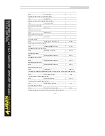
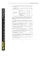
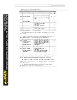
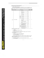
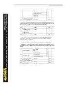
P1.30
A/B phase sequence of ABZ
incremental encoder
Forward
0
0
★
Reverse
1
This parameter is valid only for ABZ incremental encoder (P1.28 = 0) and is used to set the
A/BphasesequenceoftheABZincrementalencoder.
It is valid for both asynchronous motor and synchronous motor. The A/B phase sequence can be
obtained through "Asynchronous motor complete auto-tuning" or "Synchronous motor no-load
auto-tuning".
P1.31
Encoder installation angle
0°~359.9°
0.00
★
This parameter is applicable only to synchronous motor. It is valid for ABZ incremental encoder,
UVW incremental encoder, resolver and wire-saving UVW encoder, but invalid for SIN/COS encoder.
It can be obtained through synchronous motor no-load auto-turning or with-load auto-tuning. After
installation of the synchronous motor is complete, the value of this parameter must be obtained by
motor auto-tuning. Otherwise, the motor cannot run properly.
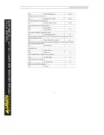
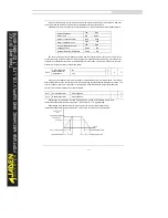
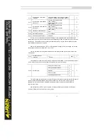
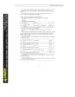
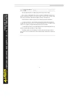
P1.32
U, V, W phase sequence of
UVW encoder
Forward
0
0
★
Reverse
1
P1.33
UVW encoder angle offset
0.0°~359.9°
0.00
★
These two parameters are valid only when the UVW encoder is applied to a synchronous motor.
They can be obtained by synchronous motor no-load auto-tuning or with-load auto-tuning. After
installation of the synchronous motor is complete, the values of these two parameters must be obtained
by motor auto-tuning. Otherwise, the motor cannot run properly.
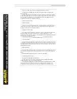
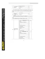
P1.34
Resolver pole pairs
1~65535
1
★
P1.35
UVW pole pairs
1~65535
4
★
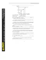
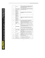
P1.36
Encoder wire-break fault
detection time
0.0s:No action; 0.1s~10.0s
0.0s
★
This parameter is used to set the time that a wire-break fault lasts.
If it is set to 0.0s, the Inverter does not detect the encoder wire-break fault.
If the duration of the encoder wire-break fault detected by the Inverter exceeds the time set in this
parameter, the Inverter reports Err20.
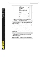
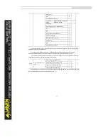
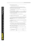
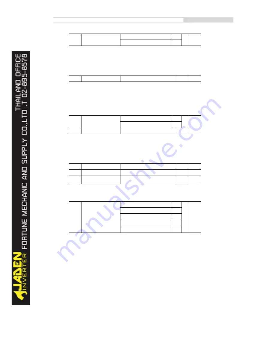
P1.37
Auto-tuningselection
No auto-tuning
0
0
★
Asynchronous motor static auto-tuning
1
Asynchronous motor complete
auto-tuning
2
Synchronous motor static auto-tuning
11
Synchronous motor complete
auto-tuning
12
Summary of Contents for DLB1-0D40S2G
Page 11: ...11 Graph 1 722 30KW product outline dimensions Graph 1 837 55KW product outline dimensions...
Page 12: ...12 Graph 1 875 110KW product outline dimensions Graph 1 9 132 160KW product outline dimensions...
Page 14: ...14 2 Wirings 2 1 Standard wiring diagrams Graph 2 8 0 4 18 5KW inverter wiring diagram...
Page 15: ...15 Graph 2 922 400KW inverter wiring diagram...
Page 159: ...159...

