-47-
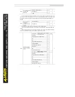
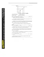
In this mode, V and F are proportional and the proportional relationship can be set in P2.13. The
relationship between V and F are also related to the rated motor voltage and rated motor frequency in
Group F1.
Assume that the voltage source input is X (0 to 100%), the relationship between V and F is:
V/F = 2 * X * (Rated motor voltage)/(Rated motor frequency)
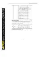
Hundred’s place:automaticvoltage regulation (AVR)function
CPU automatically optimizes DC bus voltage when grid power supply fluctuates..
0:No AVR;
1:Have AVR;
2:Have AVR but not during deceleration.
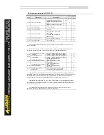
P2.01
Torque boost
0.0%~30%
-
★
P2.02
Torque boost cut-off
frequency
0.00Hz~ maximum output frequency
50.00Hz
★
To compensate the low frequency torque characteristics of V/F control, you can boost the output
voltage of the Inverter at low frequency by modifying P2.01.
If the torque boost is set to too large, the motor may overheat, and the Inverter may suffer
overcurrent.
If the load is large and the motor startup torque is insufficient, increase the value of P2.01. If the load
is small, decrease the value of P2.01. If it is set to 0.0, the Inverter performs automatic torque boost. In
this case, the Inverter automatically calculates the torque boost value based on motor parameters
including the stator resistance.
P2.02 specifies the frequency under which torque boost is valid. Torque boost becomes invalid when
this frequency is exceeded.
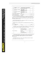
P2.03
Multi-point V/F frequency 1
(F1)
0.00Hz~P2.05
0.00Hz
★
P2.04
Multi-point V/F voltage 1 (V1)
0.0%~100.0%
0.0%
★
P2.05
Multi-point V/F frequency 2
(F2)
P2.03~P2.07
0.00Hz
★
P2.06
Multi-point V/F voltage 2 (V2)
0.0%~100.0%
0.0%
★
P2.07
Multi-point V/F frequency 3
(F3)
P2.05~ motorrated
频
(P1.04)
0.00Hz
★
P2.08
Multi-point V/F voltage 3 (V3)
0.0%~100.0%
0.0%
★
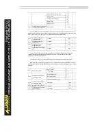
These six parameters are used to define the multi-point V/F curve.
The multi-point V/F curve is set based on the motor's load characteristic. The relationship between
voltages and frequencies is:
V1 < V2 < V3, F1 < F2 < F3
At low frequency, higher voltage may cause overheat or even burnt out of the motor and overcurrent
stall or overcurrent protection of the Inverter.
Summary of Contents for DLB1-0D40S2G
Page 11: ...11 Graph 1 722 30KW product outline dimensions Graph 1 837 55KW product outline dimensions...
Page 12: ...12 Graph 1 875 110KW product outline dimensions Graph 1 9 132 160KW product outline dimensions...
Page 14: ...14 2 Wirings 2 1 Standard wiring diagrams Graph 2 8 0 4 18 5KW inverter wiring diagram...
Page 15: ...15 Graph 2 922 400KW inverter wiring diagram...
Page 159: ...159...

