-50-
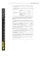
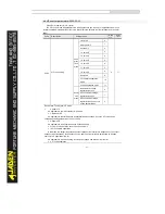
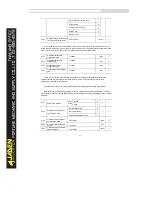
•
6: Simple PLC
If the voltage source is simple PLC mode, parameters in group PC must be set to determine the
setting output voltage.
•
7: PID
The output voltage is generated based on PID closed loop. For details, see the description of PID in
group PA.
•
8: Communication setting
The output voltage is set by the host computer by means of communication.
The voltage source for V/F separation is set in the same way as the frequency source. For details,
see P0.03. 100.0% of the setting in each mode corresponds to the rated motor voltage. If the
corresponding value is negative, its absolute value is used.
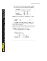
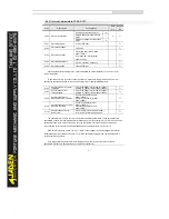
P2.15
Voltage rise time of V/F
separation
0.0s~1000.0s
0.0s
☆
P2.16
Voltage decline time of V/F
separation
0.0s~1000.0s
0.0s
☆
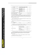
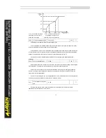
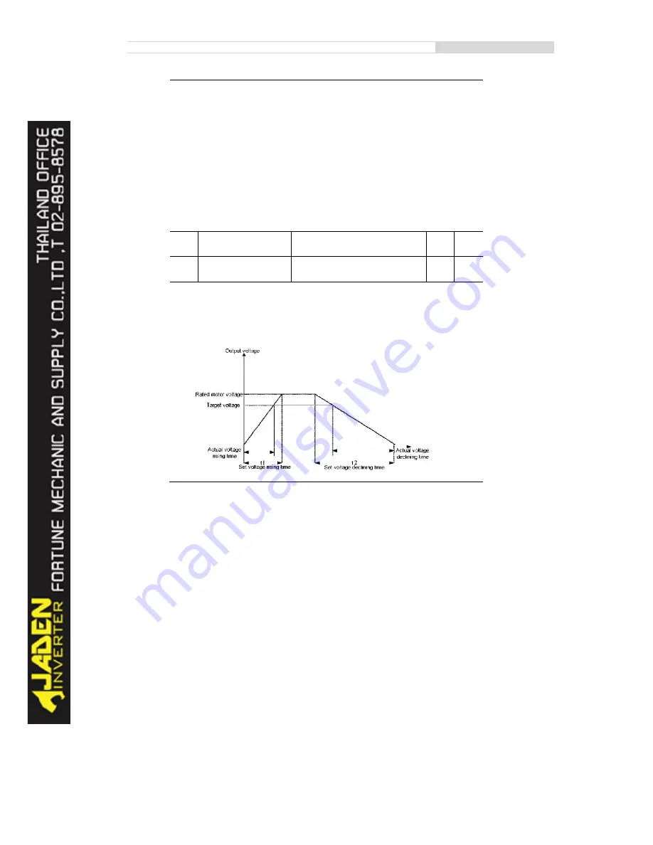
P2.15 indicates the time required for the output voltage to rise from 0 V to the rated motor voltage
shown as t1 in the following figure.
P2.16 indicates the time required for the output voltage to decline from the rated motor voltage to 0 V,
shown as t2 in the following figure.
Summary of Contents for DLB1-0D40S2G
Page 11: ...11 Graph 1 722 30KW product outline dimensions Graph 1 837 55KW product outline dimensions...
Page 12: ...12 Graph 1 875 110KW product outline dimensions Graph 1 9 132 160KW product outline dimensions...
Page 14: ...14 2 Wirings 2 1 Standard wiring diagrams Graph 2 8 0 4 18 5KW inverter wiring diagram...
Page 15: ...15 Graph 2 922 400KW inverter wiring diagram...
Page 159: ...159...

