-68-
4.7 Output terminals:P5.00-P5.22
The DLB1 provides two analog output (AO) terminals, a digital output (DO) terminal, a relay terminal and
a FM terminal (used for high-speed pulse output or open-collector switch signal output) as standard.
If these output terminals cannot satisfy requirements, use an optional I/O extension card that provides a
relay terminal (relay 2) and a DO terminal (DO2).
Code
Description
Setting range
Defa
ult
Restri
ctions
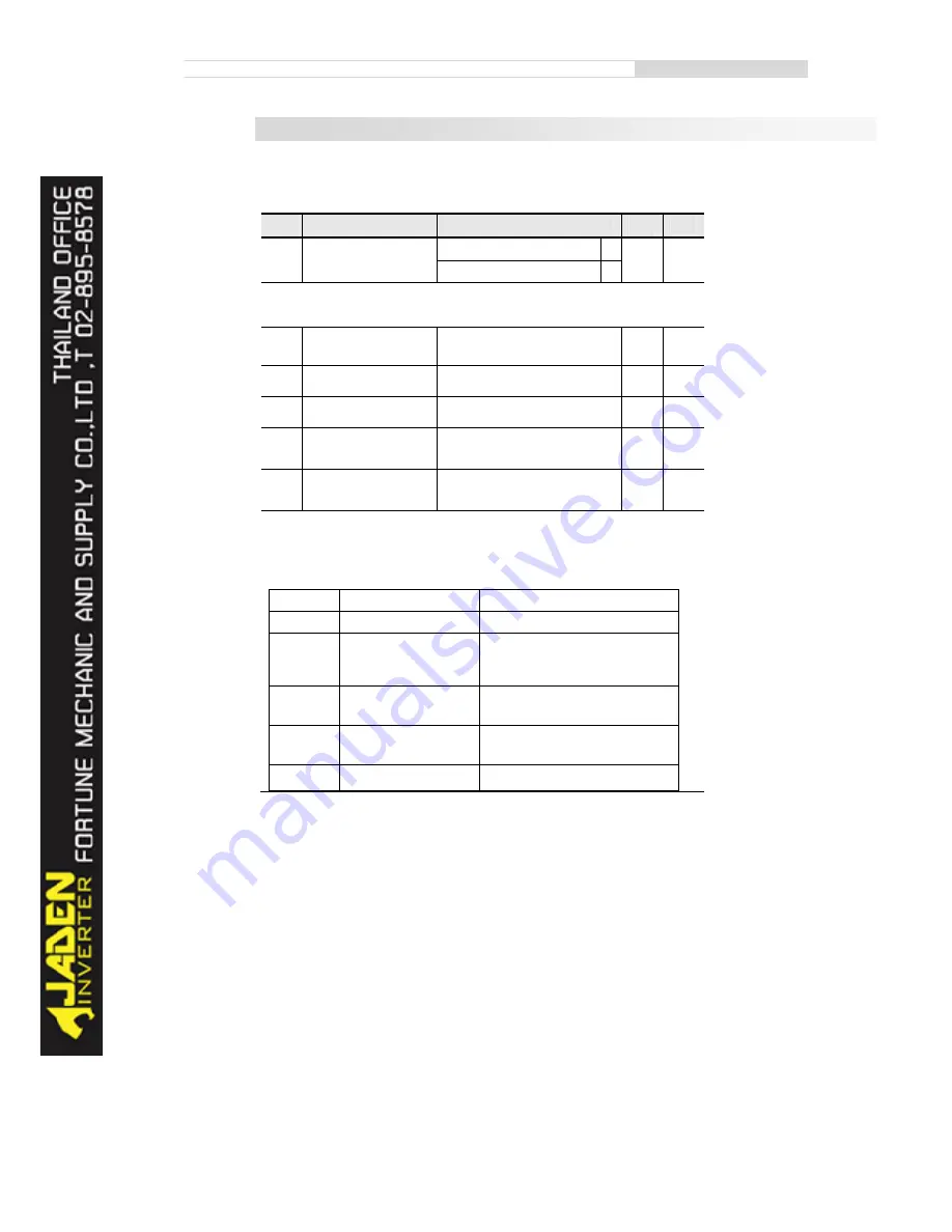
P5.00
FM output mode
Pulse output (FMP)
0
0
☆
Switch signal output (FMR)
1
The FM terminal is programmable multiplexing terminal. It can be used for high-speed pulse
output (FMP), with maximum frequency of 50 kHz. Refer to P5.06 for relevant functions of FMP. It can
also be used as open collector switch signal output (FMR).
P5.01
FMR function
(open-collector output
terminal)
0-44
0
☆
P5.02
Relay function 1
(T/A-T/B-T/C)
0-44
2
☆
P5.03
Extension card relay
function 2 (P/A-P/B-P/C)
0-44
2
☆
P5.04
DO1 function selection
(open-collector output
terminal)
0-44
1
☆
P5.05
DO2 function selection
(open-collector output
terminal)
0-44
1
☆
These five parameters are used to select the functions of the five digital output terminals.
T/A-T/B-T/C and P/A-P/B-P/C are respectively the relays on the control board and the extension card.
The functions of the output terminals are described in the following table.
Value
Function
Description
0
No output
The terminal has no function.
1
Inverter running
When the Inverter is running and has output
frequency (can be zero), the terminal
becomes ON.
2
Fault output (stop)
When the Inverter stops due to a fault, the
terminal becomes ON.
3
Frequency-level detection
FDT1 output
Refer to the descriptions of P8.19 and
P8.20.
4
Frequency reached
Refer to the descriptions of P8.21.
Summary of Contents for DLB1-0D40S2G
Page 11: ...11 Graph 1 722 30KW product outline dimensions Graph 1 837 55KW product outline dimensions...
Page 12: ...12 Graph 1 875 110KW product outline dimensions Graph 1 9 132 160KW product outline dimensions...
Page 14: ...14 2 Wirings 2 1 Standard wiring diagrams Graph 2 8 0 4 18 5KW inverter wiring diagram...
Page 15: ...15 Graph 2 922 400KW inverter wiring diagram...
Page 159: ...159...


