-82-
4.10 Auxiliary functions:P8.00-P8.53
Code
Description
Setting range
Default
Restri
ctions
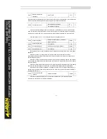
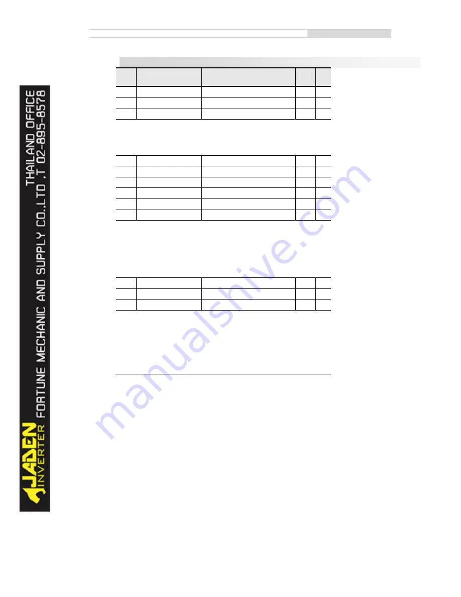
P8.00
JOG running frequency
0.00Hz~ maximum frequency
2.00Hz
☆
P8.01
JOG acceleration time
0.0s~6500.0s
20.0s
☆
P8.02
JOG deceleration time
0.0s~6500.0s
20.0s
☆
These parameters are used to define the set frequency and acceleration/deceleration time of the
Inverter when jogging. The startup mode is "Direct start" (P6.00 = 0) and the stop mode is "Decelerate
to stop" (P6.10 = 0) during jogging.
P8.03
Acceleration time 2
0.0s~6500.0s
10.0s
☆
P8.04
Deceleration time 2
0.0s~6500.0s
10.0s
☆
P8.05
Acceleration time 3
0.0s~6500.0s
10.0s
☆
P8.06
Deceleration time 3
0.0s~6500.0s
10.0s
☆
P8.07
Acceleration time 4
0.0s~6500.0s
10.0s
☆
P8.08
Deceleration time 4
0.0s~6500.0s
10.0s
☆
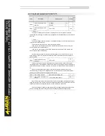
The DLB1 provides a total of four groups of acceleration/deceleration time, that is, the preceding
three groups and the group defined by P0.17 and P0.18.
Definitions of four groups are completely the same. You can switch over between the four groups
of acceleration/deceleration time through different state combinations of DI terminals. For more
details, see the descriptions of P4.01 to P4.05.
P8.09
Jump frequency 1
0.00Hz~ maximum frequency
0.00Hz
☆
P8.10
Jump frequency 2
0.00Hz~ maximum frequency
0.00Hz
☆
P8.11
Frequency jump amplitude
0.00Hz~ maximum frequency
0.00Hz
☆
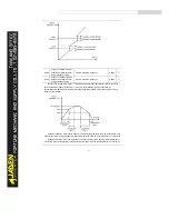
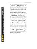
If the set frequency is within the frequency jump range, the actual running frequency is the jump
frequency close to the set frequency. Setting the jump frequency helps to avoid the mechanical
resonance point of the load.
The DLB1 supports two jump frequencies. If both are set to 0, the frequency jump function is
disabled. The principle of the jump frequencies and jump amplitude is shown in the following figure.
Summary of Contents for DLB1-0D40S2G
Page 11: ...11 Graph 1 722 30KW product outline dimensions Graph 1 837 55KW product outline dimensions...
Page 12: ...12 Graph 1 875 110KW product outline dimensions Graph 1 9 132 160KW product outline dimensions...
Page 14: ...14 2 Wirings 2 1 Standard wiring diagrams Graph 2 8 0 4 18 5KW inverter wiring diagram...
Page 15: ...15 Graph 2 922 400KW inverter wiring diagram...
Page 159: ...159...


