-92-
4.11 Fault and protection:P9.00-P9.70
Code
Description
Setting range
Default
Rest
ricti
ons
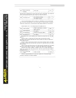
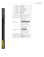
P9.00
Motor overload protection
selection
Disabled
0
1
☆
Enabled
1
P9.01
Motor overload protection
gain
0.20~10.00
1.00
☆
•
P9.00 = 0
The motor overload protective function is disabled. The motor is exposed to potential
damage due to overheating. A thermal relay is suggested to be installed between the Inverter and
the motor.
•
P9.00 = 1
The Inverter judges whether the motor is overloaded according to the inverse time-lag curve
of the motor overload protection.
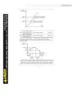
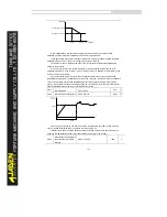
The inverse time-lag curve of the motor overload protection is:
220% x P9.01 x rated motor current (if the load remains at this value for one minute, the
Inverter reports motor overload fault), or
150% x P9.01 x rated motor current (if the load remains at this value for 60 minutes, the
Inverter reports motor overload fault)
Set P9.01 properly based on the actual overload capacity. If the value of P9.01 is set too
large, damage to the motor may result because the motor overheats but the Inverter does not
report the alarm.
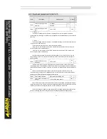
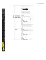
P9.02
Motor overload warning
coefficient
50%~100%
80
%
☆
This function is used to give a warning signal to the control system via DO before motor
overload protection. This parameter is used to determine the percentage, at which pre-warning is
performed before motor overload. The larger the value is, the less advanced the pre-warning will
be.
When the accumulative output current of the Inverter is greater than the value of the
overload inverse time-lag curve multiplied by P9.02, the DO terminal on the Inverter allocated
with function 6 (Motor overload pre-warning) becomes ON.
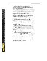
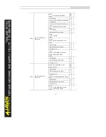
P9.03
Over-voltage stall gain
0(No stall over-voltage)~100
0
☆
P9.04
Over-voltage stall protective
voltage
120%~150%( three phase)
130%
☆
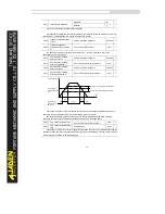
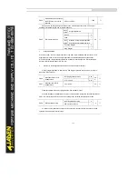
When the DC bus voltage exceeds the value of P9.04 (Overvoltage stall protective voltage)
during deceleration of the Inverter, the Inverter stops deceleration and keeps the present running
frequency. After the bus voltage declines, the Inverter continues to decelerate.
P9.03 (Overvoltage stall gain) is used to adjust the overvoltage suppression capacity of the
Inverter. The larger the value is, the greater the overvoltage suppression capacity will be.
Summary of Contents for DLB1-0D40S2G
Page 11: ...11 Graph 1 722 30KW product outline dimensions Graph 1 837 55KW product outline dimensions...
Page 12: ...12 Graph 1 875 110KW product outline dimensions Graph 1 9 132 160KW product outline dimensions...
Page 14: ...14 2 Wirings 2 1 Standard wiring diagrams Graph 2 8 0 4 18 5KW inverter wiring diagram...
Page 15: ...15 Graph 2 922 400KW inverter wiring diagram...
Page 159: ...159...


