-93-
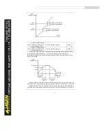
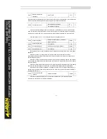
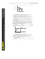
In the prerequisite of no overvoltage occurrence, set P9.03 to a small value.
For small-inertia load, the value should be small. Otherwise, the system dynamic response
will be slow. For large-inertia load, the value should be large. Otherwise, the suppression result
will be poor and an overvoltage fault may occur.
If the overvoltage stall gain is set to 0, the overvoltage stall function is disabled.
P9.05
Over-current stall gain
0~100
20
☆
P9.06
Over-current stall
protective current
100%~200%
150%
☆
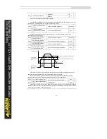
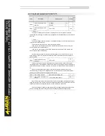
When the output current exceeds the overcurrent stall protective current during acceleration/
deceleration of the Inverter, the Inverter stops acceleration/deceleration and keeps the present
running frequency. After the output current declines, the Inverter continues to
accelerate/decelerate.
P9.05 (Overcurrent stall gain) is used to adjust the overcurrent suppression capacity of the
Inverter. The larger the value is, the greater the overcurrent suppression capacity will be. In the
prerequisite of no overcurrent occurrence, set tP9.05 to a small value.
For small-inertia load, the value should be small. Otherwise, the system dynamic response
will be slow. For large-inertia load, the value should be large. Otherwise, the suppression result
will be poor and overcurrent fault may occur.
If the overcurrent stall gain is set to 0, the overcurrent stall function is disabled.
P9.07
Short-circuit to ground upon
power- on
Disabled
0
1
☆
Enabled
1
It is used to determine whether to check the motor is short-circuited to ground at power-on of
the Inverter. If this function is enabled, the Inverter's UVW will have voltage output a while after
power-on.
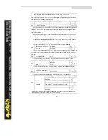
P9.09
Fault auto reset times
0~20
0
☆
It is used to set the times of fault auto resets if this function is used. After the value is
exceeded, the Inverter will remain in the fault state.
P9.10
DO action during fault auto
reset
No action
0
0
☆
Action
1
It is used to decide whether the DO acts during the fault auto reset if the fault auto reset
function is selected.
P9.11
Time interval of fault auto
reset
0.1s~100.0s
1.0s
☆
It is used to set the waiting time from the alarm of the Inverter to fault auto reset.
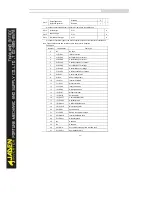
P9.12
Input phase loss
protection
One’s place
Input phase loss protection
11
☆
Disabled
0
Enabled
1
Ten’s place
Contactor energizing protection
Disabled
0
Enabled
1
It is used to determine whether to perform input phase loss or contactor energizing protection.
(Only available for DLB1 series inverter over 18.5KW models)
Summary of Contents for DLB1-0D40S2G
Page 11: ...11 Graph 1 722 30KW product outline dimensions Graph 1 837 55KW product outline dimensions...
Page 12: ...12 Graph 1 875 110KW product outline dimensions Graph 1 9 132 160KW product outline dimensions...
Page 14: ...14 2 Wirings 2 1 Standard wiring diagrams Graph 2 8 0 4 18 5KW inverter wiring diagram...
Page 15: ...15 Graph 2 922 400KW inverter wiring diagram...
Page 159: ...159...


