-94-
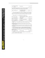
P9.13
Output phase loss
protection selection
Disabled
0
1
☆
Enabled
1
It is used to determine whether to perform output phase loss protection.
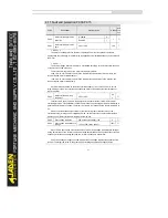
P9.14
1st fault type
0~51
-
●
P9.15
2nd fault type
0~51
-
●
P9.16
3rd (latest) fault type
0~51
-
●
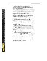
It is used to record the types of the most recent three faults of the Inverter. 0 indicates no
fault. For possible causes and solution of each fault, refer to Chapter 6.
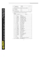
Fault types:
Number
Fault display
Fault type
0
No
No fault
1
1=E.IGbt
IGBT protection
2
2=E.oCAC
Acceleration over current
3
3=E.oCdE
Ceceleration over current
4
4=E.oCCo
Constant speed over current
5
5=E.oUAC
Acceleration over voltage
6
6=E.oUdE
Deceleration over voltage
7
7=E.oUCo
Constant speed over voltage
8
8=E.CPF
Control power fault
9
9=E.LU
Under voltage fault
10
10=E.oL1
Inverter overload
11
11=E.oLt
Motor overload
12
12=I.PHO
Input phase loss
13
13=O.PHo
Output phase loss
14
14=E.oH1
Module overheat
15
15=E.EIoF
External fault
16
16=E.CoF1
Communication fault
17
17=E.rECF
Contactor fault
18
18=E.HALL
Current detection fault
19
19=E.tUnE
Motor tuning fault
20
20=E.PG1
Encoder fault
21
21=E.EEP
EEPROM read & write fault
22
22=E.HArd
Inverter hardware fault
23
23=E.SHot
Grounding fault
24
No
Reserved
25
No
Reserved
26
26=E.ArA
Accumulative running time reached fault
27
27=E.USt1
User defined fault 1
Summary of Contents for DLB1-0D40S2G
Page 11: ...11 Graph 1 722 30KW product outline dimensions Graph 1 837 55KW product outline dimensions...
Page 12: ...12 Graph 1 875 110KW product outline dimensions Graph 1 9 132 160KW product outline dimensions...
Page 14: ...14 2 Wirings 2 1 Standard wiring diagrams Graph 2 8 0 4 18 5KW inverter wiring diagram...
Page 15: ...15 Graph 2 922 400KW inverter wiring diagram...
Page 159: ...159...


