-95-
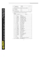
28
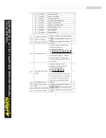
28=E.USt2
User defined fault2
29
29=E.APA
Power-on timereached
30
30=E.ULF
Load becoming 0 fault
31
31=E.PID
PID feedback lost duringrunning
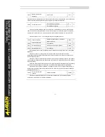
40
40=E.CbC
IGBT current limiting fault
41
41=E.tSr
Running motor switchover fault
42
42=E.SdL
Speed deviation too large
43
43=E.oSF
Motor over speed
45
45=E.oHt
Motor over heat
51
51=E.PoSF
Initial position fault
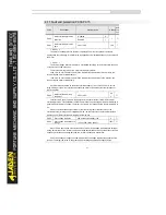
P9.17
Frequency upon 3rd fault
It displays the frequency when the latest fault
occurs.
●
P9.18
Current upon 3rd fault
It displays the current when the latest fault
occurs.
●
P9.19
Bus voltage upon 3rd fault
It displays the bus voltage when the latest
fault occurs.
●
P9.20
DI status upon 3rd fault
It displays the status of all DI terminals
whenthe latest fault occurs.
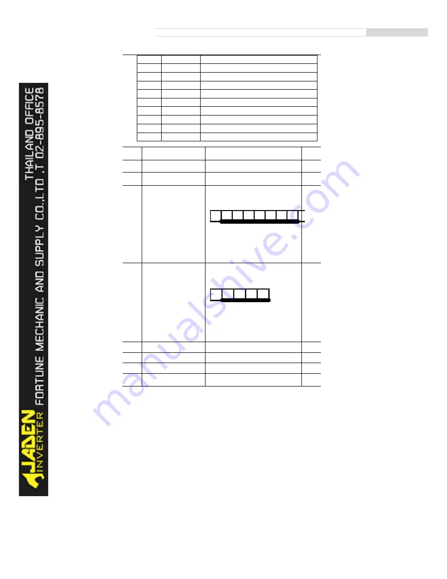
The sequence is as follows:
If a DI is ON, the setting is 1. If the DI is
OFF, the setting is 0. The value is the
equivalent decimal number converted from
the DI status.
●
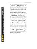
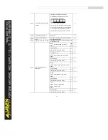
P9.21
Output terminal status upon
3rd fault
It displays the status of all output
terminalswhen the latest fault occurs.
The sequence is as follows:
If an output terminal is ON, the setting is 1.
If the output terminal is OFF, the setting is
0. The value is the equivalent decimal
number converted from the DI statuses.
●
P9.22
3rd faultinverter status
Reserved
●
P9.23
Power-on time upon 3rd
fault
It displays the present power-on time when
the latest fault occurs.
●
P9.24
Running time upon 3rd fault
It displays the present running time when the
latest fault occurs.
●
P9.27
Frequency upon 2nd fault
It displays the frequency when the latest fault
occurs.
●
BIT9
BIT8
BIT7
BIT6
BIT5
BIT4
BIT3
BIT2
BIT1
DI2
DI3
DI4
DI5
DI6
DI7
DI8
DI9
DI0
BIT4
BIT3
BIT2
BIT1
BIT0
FMP
REL1
REL2
DO1
DO2
Summary of Contents for DLB1-0D40S2G
Page 11: ...11 Graph 1 722 30KW product outline dimensions Graph 1 837 55KW product outline dimensions...
Page 12: ...12 Graph 1 875 110KW product outline dimensions Graph 1 9 132 160KW product outline dimensions...
Page 14: ...14 2 Wirings 2 1 Standard wiring diagrams Graph 2 8 0 4 18 5KW inverter wiring diagram...
Page 15: ...15 Graph 2 922 400KW inverter wiring diagram...
Page 159: ...159...


