background image

DCF-S-0126-2A (06.04)

Japan Aviation Electronics Industry, Ltd.

Connector Div. Production Engineering Dept.

日本航空電子工業株式会社コネクタ事業部生産技術部

Number

番号

T700460

Page

6

10

JAE Connector Div. Proprietary.
Copyright

©

2020, Japan Aviation Electronics Industry, Ltd.

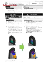
4.圧着作業

4.Crimping

4-1.ハンドルの開放

4-1.Handles opening

コンタクトを工具に挿入する前にハンドルを開
放状態にして下さい。

Open the handles before inserting a contact.

ハンドルが開かない場合は、ラチェットが開放
されるまでハンドルを握り締めて下さい。

In case the handle does not open, close the
handles until ratchet released.

注意

CAUTION

アンビルが開閉します。怪我の原因となりますの
で、クリンパとアンビルの間の隙間に指を入れない
で下さい。

The crimper moves OPEN / CLOSE.
Never put fingers into opening between the
crimper and anvil.

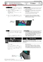
4-2.コンタクトのセット

4-2.Contact setting

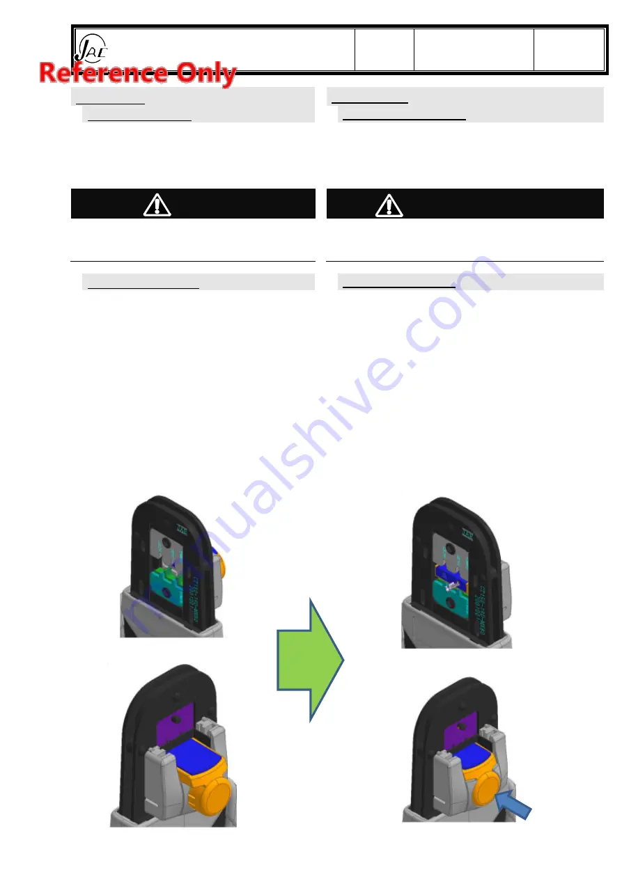
背面から、ロケータを押して、コンタクトセット
部を前面に出します。

From the back side, push the locator and pull out
the contact set part to the front.

ロケータを背面から押したまま、使用する圧着
部にコンタクトを奥まで挿入します。

With the locator pressed from the back, insert the
contact all the way into the crimping part to be
used.

ロケータを後に戻してください。

Please move the locator backwards.

本工具は、圧着部が 2 ヶ所あります。
コンタクトと電線サイズにより使い分けて下さ
い。7項圧着条件を参照して下さい。
間違った位置に適用で無いコンタクトを挿入
し、圧着すると工具を破損する可能性があり
ます。
尚、電線サイズの表示は、被覆クリンパにあり
ます。

There are two crimping parts of this tool.
Please use properly according to contact and wire
size. Refer to 7 crimp condition.
Insert a contact that is not applied to the wrong
position and crimp it may damage the tool.
In addition, the display of electric wire size is on
the cover crimper.

6/10

Summary of Contents for CT150-19D-MX80

Page 1: ...neering Dept Prepared Checked Approved PL Approved K KOIDE N SAKAI C YANOSAKI JAE Connector Div Proprietary Copyright 2020 Japan Aviation Electronics Industry Ltd CRIMPING HAND TOOL CT150 19D MX80 OPE...

Page 2: ...not followed WARNIN G A warning indicates an operation that could cause serious personal injury or fatal wound if precautions are not followed CAUTION A caution indicates an operation that could cause...

Page 3: ...ur customer support department Please work while getting enough rest when you use this tool for a long time Injury might be caused for the body CAUTION Crimper and anvil can pinch the fingers Never pu...

Page 4: ...Preparation of Crimping 5 4 4 Crimping 6 4 1 4 1 Handles opening 6 4 2 4 2 Contact setting 6 4 3 4 3 Wire setting 7 4 4 4 4 Crimping 7 4 5 4 5 Take out 8 5 5 Check of Crimped Contacts 8 6 6 Maintenanc...

Page 5: ...refer to para 7 Check that each wire conductor is not damaged nor scratched Set any disarrayed conductors straight prior to the crimping operation Don t use one with cutoff and the crack in the wick...

Page 6: ...SE Never put fingers into opening between the crimper and anvil 4 2 4 2 Contact setting From the back side push the locator and pull out the contact set part to the front With the locator pressed from...

Page 7: ...applying it too much and note that it is likely to become defective crimping 4 4 4 4 Crimping While holding the wire and contact position as set close the handles gradually with being careful not to m...

Page 8: ...ight is satisfied with crimp standard refer to para 7 2 2 2 Wire strands tip is extended from the wire barrel 3 3 Wire insulation does not intrude into the wire barrel 4 4 Wire strands do not protrude...

Page 9: ...hand tool has a product life of 50 000 times Repair will not be performed except for repair of spring etc In addition inspection work such as presence of abnormality check of wear etc will be done 4...

Page 10: ...l name Indication on tool 1 Wire size Insulation diameter Crimp height range 2 Insulation height 3 Crimp strength 4 CT150 19D MX80 K4 0 35 0 35sq 1 2 1 4 0 75 0 81 mm 1 6mm 50N K4 0 5 0 5sq 1 4 1 6 0...

Reviews: