8
ADwin-Gold
Hardware Manual, Version 2.3
ADwin
Processor and memory
Analog inputs
Analog outputs
Digital inputs and outputs
Trigger input (EVENT)
2.2 The
ADwin-Gold System
The
ADwin
-
Gold
system is equipped with the digital
32 bit signal processor
ADSP 21062 (SHARC) from Analog Devices with floating point and integer
processing. It is responsible for the complete measurement data acquisition,
online processing, and signal output, and makes it possible to process
instantaneously sample rates of up to several 100 kHz.
The on-chip
memory with 256 kB
has a very short access time of 25 ns and
is large enough to hold the complete
ADwin
operating system, the
ADbasic
processes and all variables.
In order to get maximum access times, all inputs and outputs are memory-
mapped in the external memory section of the DSP. For buffering larger quantities
of data the DSP uses an external memory (DRAM) of 4 MB (optional 16 MB or
32 MB).
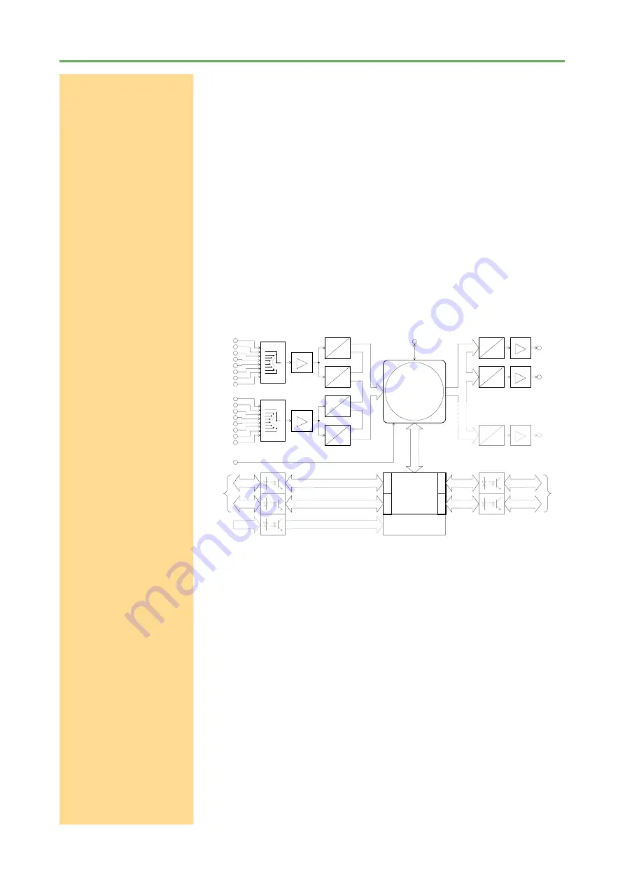
The system has
16 analog inputs
with BNC sockets, which are div
i
ded into
two groups and in each group is connected to one multiplexer. These two
outputs are optionally converted by a 12-bit or 16-bit analog-to-digital converter
(ADC), (see Figure: Bock diagram
ADwin-Gold
). With the 12-bit ADCs it is
possible to sample
very fast
with the 16-bit ADCs
highly accurately
.
The standard version of the
ADwin-Gold
system is equipped with
two
(optio-
nal eight)
analog outputs
with an output voltage range of -10 to +10 Volt and
a 16-bit resolution. You can synchronize the output of the voltage of all DACs
per software.
In order to smooth the output signal, it passes through a low-pass filter with a
cut-off frequency of f
c
= 300 kHz.
32 digital inputs or outputs
are available on two 25-pin D-Sub connectors.
They can be programmed in groups of eight as inputs or outputs. The inputs or
outputs are TTL-compatible.
ADwin
-
Gold
has a trigger input (EVENT, see also chapter 5.2 „Digital Inputs
and Outputs“). Processes can be triggered by a signal and are completely
processed afterwards. (see
ADbasic
manual, chapter: Structure of the
ADbasic
Program).
four 32 bit counter
16 bit, 10µs
16 bit, 10µs
12 bit, 0.8µs
12 bit, 0.8µs
A
D
A
D
A
D
A
D
MUX
MUX
IN 1
IN 3
IN 5
IN 7
IN 9
IN 11
IN 13
IN 15
IN 2
IN 4
IN 6
IN 8
IN 10
IN 12
IN 14
IN 16
D
A
SHARC
™
ADSP 21062
from Analog Devices
with 4/16/32 MByte
external DRAM
D
A
16bit
16bit
OUT 1
OUT 2
32 digital I/Os,
programmable
as in- or outputs
8
I/O
8
I/O
8
I/O
8
I/O
CONN. 1
(DIGITAL IN)
CONN. 2
(DIGITAL OUT)
to PC
EVENT
PGA
G = 1, 2, 4, 8
+
-
PGA
G = 1, 2, 4, 8
+
-
D
A
16bit
OUT 8
. . . . .
. . . . .
8 bit
8 bit
8 bit
8 bit
8 bit
8 bit
OP
+
-
OP
+
-
OP
+
-
. . . . .
8 bit
8 bit
Note: shaded components are optional.
A/CLK
B/DIR
CLR/L
Figure 2-2: Block diagram
ADwin-Gold
2.2 The ADwin-Gold System


