The LS bus
ADwin
2
ADwin
LS Bus, Manual version 1.0, September 2006
2 The LS bus
The LS bus is a bi-directional serial bus with 5 MHz clock rate. The bus
connects an
ADwin
system via its LS bus interface with up to 15 LS bus
modules.
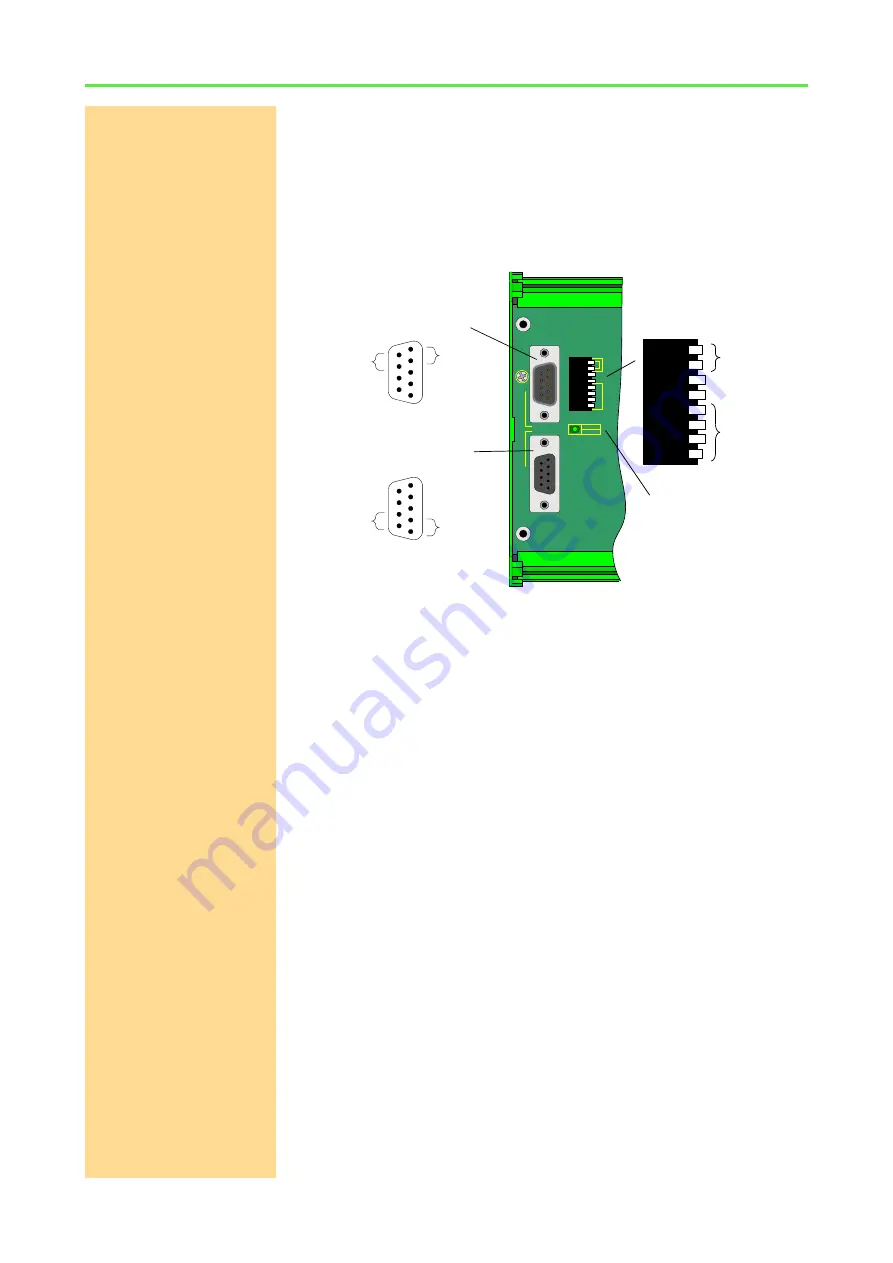
shows the standard connections of an LS bus module: Bus input and
output with LED, protection earth PE, DIP switch for bus termination and bus
address.
The bus is set up as line connection, i.e. the interface and the LS bus modules
are connected to each other via two-way links. Each module has a female
DSub connector (9-pole) as bus input and a male DSub connector (9-pole) as
bus output. The maximum bus length is 5m.
The LED besides bus Bus input/output indicates data traffic on the LS bus:
– Green LED: The module receives or sends data.
– Red LED: Data for other modules is sent on the bus.
– LED off: No data traffic.
Bus Termination
The bus termination on the last module of the LS bus must be activated with
the DIP switches
Term.
, deactivated on all other modules. To activate the bus
termination both DIP switches are set down.
Bus address
Each module on the LS bus is addresses via its bus address; therefore the
address must be unique for each module.
The bus address is set manually with the DIP switch block on the PCB besides
the bus connectors (see
). Using the 4 DIP switches
Device
Address
the address may be set to 1…15. The setting is: 1 = DIP switch down, 0 = DIP
switch up.
Address 0 disables the module. Even if a module is disabled, the foloowing
modules on the LS bus receive all bus data.
PE
BU
S I
N
BUS O
U
T
gn / active
rd / ready
Te
rm
.
De
vi
ce
A
d
d
re
ss
1
2 3
4
DIP switch block
5
4
3
2
1
9
8
7
6
SIGNAL GND
RESERVED
SIGNAL HIGH
RESERVED
SIGNAL LOW
RESERVED
RESERVED
1
2
3
4
5
6
7
8
9
SIGNAL HIGH
RESERVED
SIGNAL GND
SIGNAL LOW
RESERVED
RESERVED
RESERVED
Input LS bus
(male)
Output LS bus
(female)
B u s
termination
B u s
address
LED


