ADwin-Pro II
Hardware, manual Dec. 2018
123
Pro II: Digital-I/O Modules
Pro II-OPT-16 Rev. E
ADwin
5.7.6 Pro II-OPT-16 Rev. E
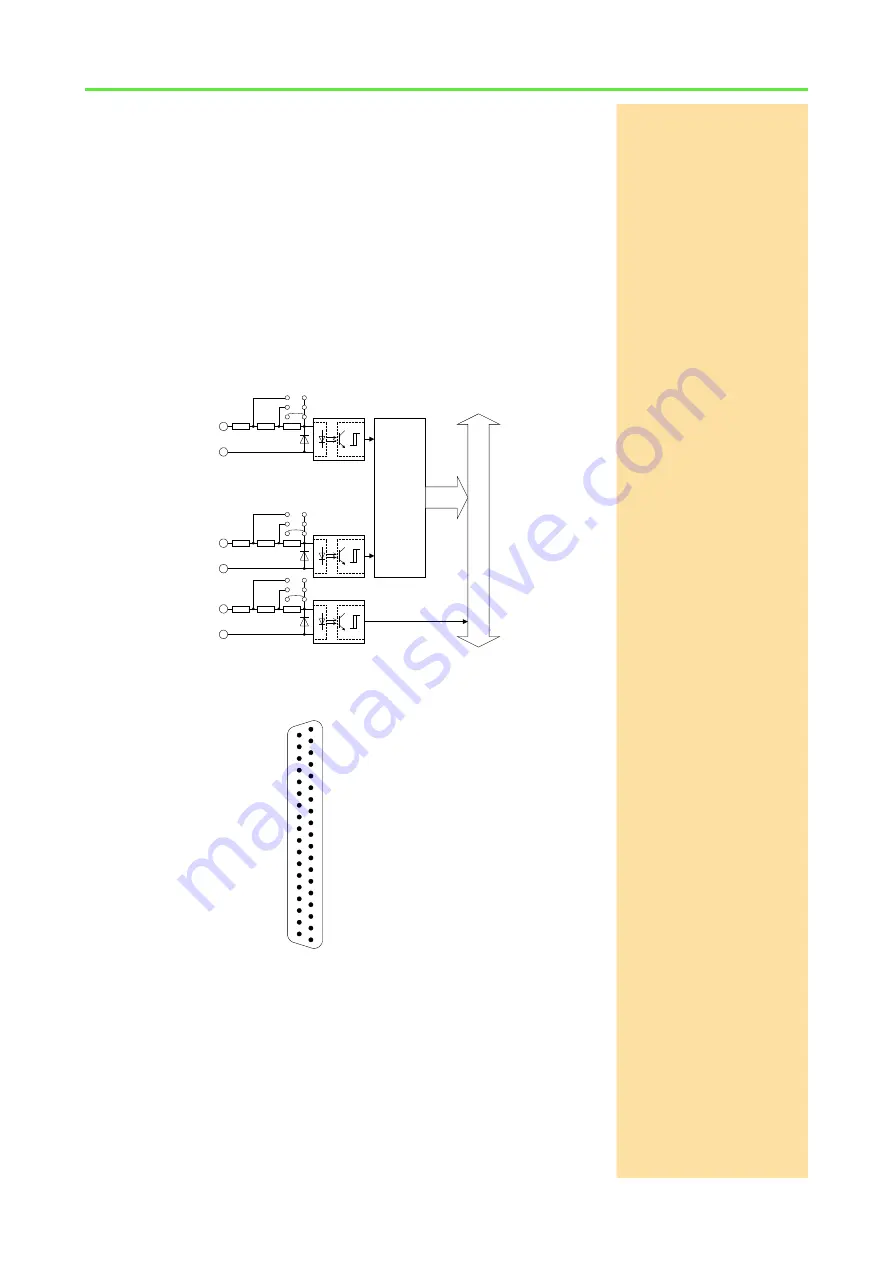
The input module Pro II-OPT-16 Rev. E provides 16 channels of optically iso-
lated digital inputs. The input voltage range can be set by jumpers (5V, 12V,
24V). The default setting of the input voltage range is 24V. The switching time
of only 100ns allows the sampling of high-speed digital inputs.
The module can automatically monitor the edges of input channels, which is
performed with a frequency of 100MHz. With every change, the current input
levels are saved together with a time stamp in a FIFO; up to 511 of those value
pairs (input level and time stamp) can be stored. The FIFO data can be read
and processed.
In addition, one can query whether a positive or negative edge has occurred
at the input channels.
Each channel is optically isolated from the system circuitry and from the other
inputs. The event-input is optically isolated from the system as well.
Fig. 104 – Pro II-OPT-16 Rev. E: Block diagram
Fig. 105 – Pro II-OPT-16 Rev. E: Pin assignment
ADwi
n-P
ro
bus
..............
..............
0
15
Data
Register Data
EVENT
+
-
1k51
1k
510
24V
12V
5V
+
-
1k51
1k
510
24V
12V
5V
+
-
1k51
1k
510
24V
12V
5V
DIG IN, BIT 0 (-)
DIG IN, BIT 1 (-)
DIG IN, BIT 2 (-)
DIG IN, BIT 3 (-)
DIG IN, BIT 4 (-)
DIG IN, BIT 5 (-)
DIG IN, BIT 6 (-)
DIG IN, BIT 7 (-)
DIG IN, BIT 8 (-)
DIG IN, BIT 9 (-)
DIG IN, BIT 10 (-)
DIG IN, BIT 11 (-)
DIG IN, BIT 12 (-)
DIG IN, BIT 13 (-)
DIG IN, BIT 14 (-)
DIG IN, BIT 15 (-)
DGND
EVENT IN (+)
DIG IN, BIT 0 (+)
DIG IN, BIT 1 (+)
DIG IN, BIT 2 (+)
DIG IN, BIT 3 (+)
DIG IN, BIT 4 (+)
DIG IN, BIT 5 (+)
DIG IN, BIT 6 (+)
DIG IN, BIT 7 (+)
DIG IN, BIT 8 (+)
DIG IN, BIT 9 (+)
DIG IN, BIT 10 (+)
DIG IN, BIT 11 (+)
DIG IN, BIT 12 (+)
DIG IN, BIT 13 (+)
DIG IN, BIT 14 (+)
DIG IN, BIT 15 (+)
DGND
RESERVED
EVENT IN (-)
19
18
17
16
15
14
13
12
11
10
9
8
7
6
5
4
3
2
1
37
36
35
34
33
32
31
30
29
28
27
26
25
24
23
22
21
20


