Pro II: Digital-I/O Modules
Pro II-COMP-16 Rev. E
ADwin
136
ADwin-Pro II
Hardware, manual Dec. 2018
– Standard hysteresis
The hysteresis refers to the set threshold. The channel bit is set to 1 if
the threshold plus hysteresis is exceeded, and is reset to 0 if the signal
falls below the threshold minus hysteresis.
The hysteresis can be set to the following values. Until Rev. E0
2
: 0mV,
±17mV, ±33mV, ±55mV, or ±100mV; since Rev. E0
3
: 0mV, ±34mV,
±66mV, ±110mV, ±200mV.
You can the hysteresis for groups of 4 channels (1…4, 5…8, 9…12,
13…16), but not for a single channel. Comparator hold and standard
hysteresis cannot be combined.
– Free hysteresis
To use other, especially a greater hysteresis than standard hysteresis,
you have to combine a channel pair (1,2 / … / 15, 16). The signal must
be connected to both channels. The comparator bit of the channel pair
is set to 1, if the signal exceeds the thresholds of both channels. Accord-
ingly, the comparator bit is set to 0 if the signal falls below the thresholds
of both channels.
The channels being used for free hysteresis can additionally be com-
bined with comparator hold or standard hysteresis.
– Comparator filter
You can enable a filter, which is located behind the comparators, in order
to suppress single spikes. The number of spikes should be small com-
pared to the pulse width of the signal.
The filter settings apply to all channels. Each channel has its own filter.
After power-up all filters are disabled.
The filter duration can be set in a range from 20ns to 1.31ms and should
be somewhat longer than the expected width of spikes.
The filter duration determines how long a comparator output must be 1
to set the channel bit to 1. The timing filter increments in clocks of 20ns
until the target value is reached; if the comparator output is 0 the counter
is decremented. In order to fall below a threshold, the same procedure
is processed in reverse.
The filter can be combined with standard hysteresis and free hysteresis,
but is not suited for combination with comparator hold.
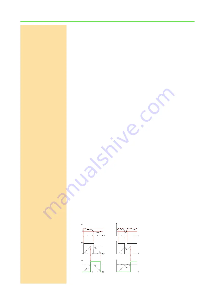
The following figure shows filtering of 2 example signals, the left one
without, the right one with a spike. The filter delays the edge of the re-
sulting signal by the filter duration plus the double length of the spike’s
length.
Fig. 124 – Pro II-COMP-16 Rev. E: Comparator filter
t
U
Komp
U
T+
U
T-
t
U
ein16
t
U
Komp
t
U
aus16
U
T+
U
T-
t
U
ein16
t
U
aus16
Input signal
Comparator signal
filtered signal


