ADwin-Pro II
Hardware, manual Dec. 2018
33
Pro II: Multi-IO Modules
Pro II-MIO-4-ET1 Rev. E
ADwin
The output voltage range of the DACs is set to ±10V bipolar and can’t be
changed. Offset and gain are adjusted by software (see chapter 6 "Calibra-
tion").
The outputs are available on a 37-pin D-Sub female connector; for pin assign-
ment see fig. 17.
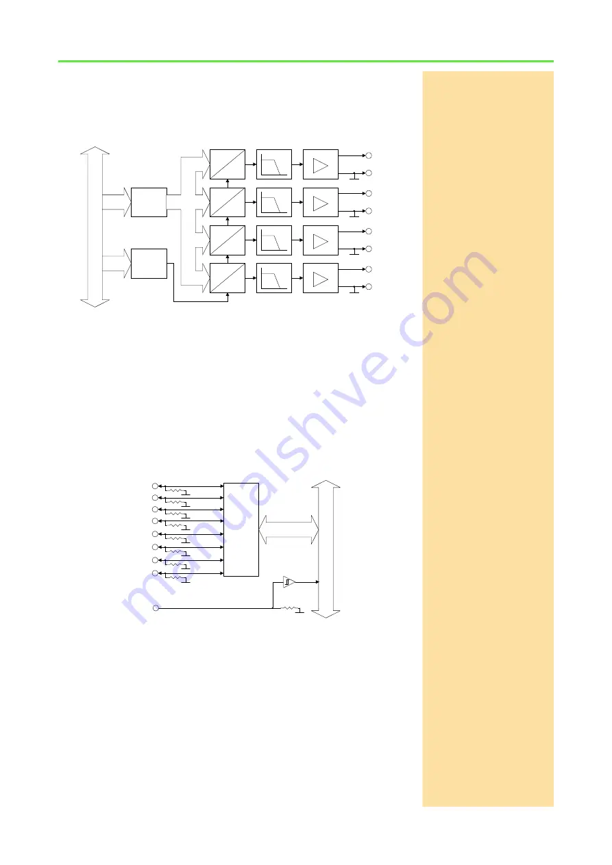
Fig. 24 – Pro II-MIO-4-ET1 Rev. E: Block diagram of analog outputs
Digital Inputs / Outputs
The digital input/output module Pro II-MIO-4-ET1 Rev. E provides 8 pro-
grammable digital input and output channels with TTL levels. The channels
can be configured as blocks of 4 as inputs or outputs by
ADbasic
instructions.
The channels are configured as inputs after power up.
Via the trigger input EVENT a signal can trigger a process, which will be pro-
cessed at once and completely (see
ADbasic
manual).
The digital channels are available on a 37-pin D-Sub female connector; for pin
assignment see fig. 17.
Fig. 25 – Pro II-MIO-4-ET1 Rev. E: Block diagram of digital channels
Transistor Outputs
The module Pro II-MIO-4-ET1 Rev. E provides 4 channels of galvanically iso-
lated transistor outputs. The outputs switch to V
CC
.
The common switching voltage V
CC
has to be provided by an external power
supply at the pins
EXT
VCC
and
EXT
GND
. Please not that
EXT
GND
is also used
for optocouple inputs.
The channels as well as the event-input are optically isolated from system cir-
cuitry.
2
ADwi
n-P
ro
bus
Addr.
Data
Data
Register
Address
Decoder
InAmp
+
-
D
A
1
3
4
LPF
InAmp
+
-
LPF
InAmp
+
-
LPF
InAmp
+
-
LPF
D
A
D
A
D
A
Data
AGND
AGND
AGND
AGND
ADwin-Pro
II
bus
0
1
7
2
3
6
EVENT
Data
Register
Data
10k
10k
10k
10k
10k
10k
10k
5
4
10k
10k


