ADwin-Pro II
Hardware, manual Dec. 2018
52
Pro II: Analog Input Modules
ADwin
5.5 Pro II: Analog Input Modules
This section describes analog input modules for
ADwin-Pro II
.
Analog input modules for
ADwin-Pro I
be found in the manual "ADwin-Pro
Hardware" on page 18 ff.
Note for open-ended inputs
Open-ended inputs can cause errors - above all in an environment where inter-
ferences may occur. You can avoid open-ended inputs this way:
– Separate unused inputs from open-ended lines.
– Apply a specified level (for instance GND) to unused inputs. Make the
connection as close to the connector as possible.
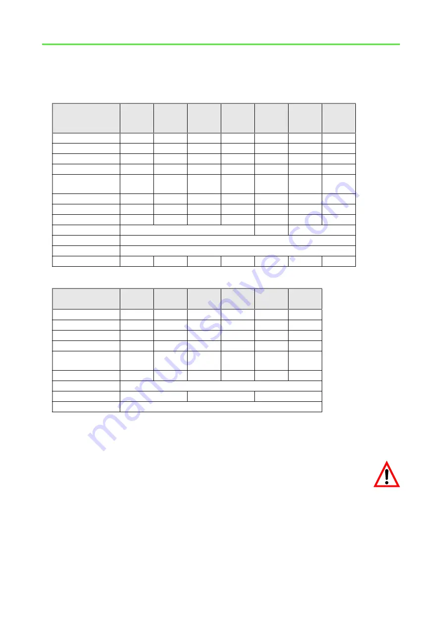
Module name
Revision
E
E
E
E
E
E
E
Number ADC
1
1
1
1
1
1
1
Resolution [Bit]
18
18
18
18
18
18
18
Max. conv. time [µs]
2
2
2
2
2
2
2
max. sampl. rate
[ksample/s]
500
500
500
500
500
500
500
Channels diff.
8
8
16
16
16
8
–
Channels sng. end.
–
–
32
32
–
–
–
Channels 8B
–
–
–
–
–
8
16
Meas. range
±
10V
±
20mA
±
10V
Gain
1, 2, 4, 8
Calibration
by software
TiCo
processor
–
TiCo1
–
TiCo1
–
–
–
page
Module name
Revision
E
E
E
E
E
E
Number ADC
4
8
4
8
4
8
Resolution [Bit]
14
14
16
16
18
18
Max. conv. time [µs]
0.02
0.02
0.25
0.25
2
2
max. sampl. rate
[ksample/s]
50000
4
×
50000
8
×
25000
4000
4000
500
500
Channels diff.
4
8
4
8
4
8
Meas. range
±
10V
Gain
1
1, 2, 4, 8
1
Calibration
by software
page


