ADwin-Pro II
Hardware, manual Dec. 2018
89
Pro II: Analog Input Modules
Pro II-AIn-F-8/18 Rev. E
ADwin
5.5.11 Pro II-AIn-F-8/18 Rev. E
The analog input module Pro II-AIn-F-8/18 Rev. E has 8 Fast-ADC of 18 Bit
and 8 differential inputs. The inputs are galvanically isolated from each other
as well as from other modules.
The inputs are available with the following connectors:
– Pro II-AIn-F-8/18: shielded LEMO female connectors, CAMAC Euro-
pean norm.
– Pro II-AIn-F-8/18-L2: shielded LEMO female connectors, 2-pole,
CAMAC European norm.
– Pro II-AIn-F-8/18-D: D-Sub female connector 37-pin.
– Pro II-AIn-F-8/18-B: BNC connectors.
The module Pro II-AIn-F-8/18 Rev. E has input voltage range of ±10V. The
adjustment of gain and offset is made by software. (see chapter 6 "Calibra-
tion").
The module can perform a simultaneous conversion on all channels using a
sequence control. This disburdens–compared to single measurements with
the instruction
P2_ADCF
–the processor module, which only reads and proces-
ses the converted measurement values. The conversion can be either trigge-
red periodically with regular time delays or by external event signals.
The module can control an upper and lower limit for each channel separately.
In order to use a channel as single-ended input, connect the input signal to the
plus pin and ground to the minus pin.
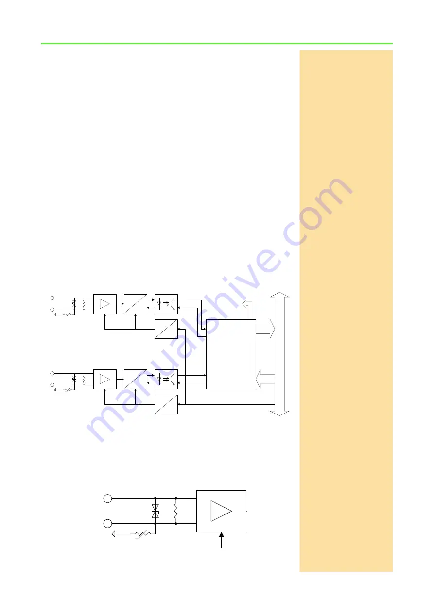
Fig. 74 – Pro II-AIn-F-8/18 Rev. E: Block diagram
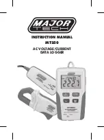
As ground connection the enclosure’s ground (PE) is available. All analog
inputs are galvanically isolated from enclosure’s ground.
With module versions -L2 (2-pole Lemo) and -D (D-Sub connector), the enclo-
sure’s ground is also available at the shield of the connectors.
Fig. 75 – Pro II-AIn-F-8/18 Rev. E: Input circuitry
ADwin-Pro
II
bus
.
.
.
addr.
data
Glue-
Logic
(address decoder,
sequence control)
A
D
A
D
DC
DC
DC
DC
.
.
.
.
.
.
.
.
.
.
.
.
V
1
Buffer
+
-
+
-
36V
50V
660k
Front (PE)
V
8
Buffer
+
-
+
-
36V
50V
660k
Front (PE)
V
1
Buffer
+
-
+
-
36V
50V
660k
Front (PE)


