ADwin-Pro II
Hardware, manual Dec. 2018
201
Pro II: Extension and Interface Modules
Pro II-SENT-6 Rev. E
ADwin
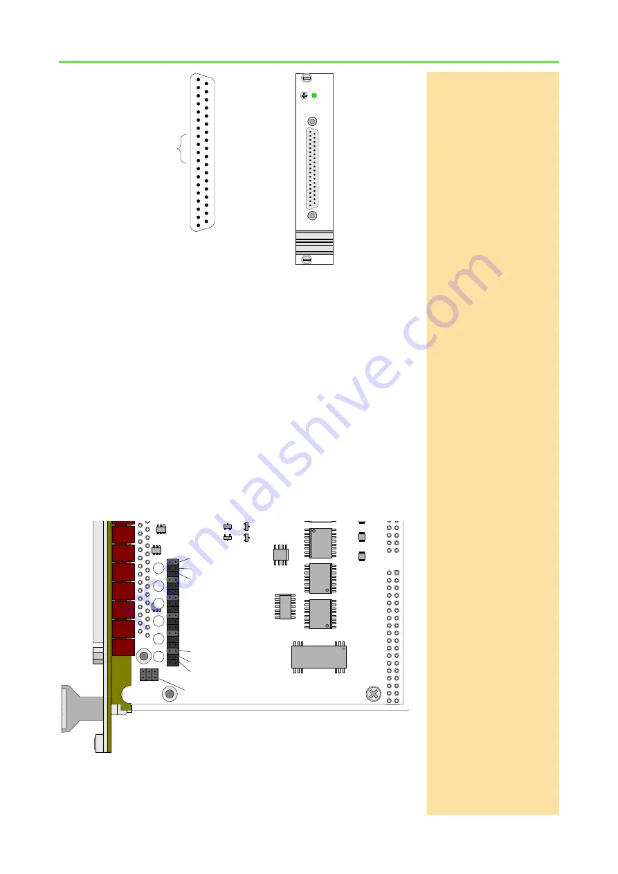
Fig. 170 – Pro II-SENT-6 Rev. E: Pin assignment and front panel
Supply voltage
Via the connected pins
Vcc
SENT
In
, you can insert a supply voltage 5 Volt of
up to 400mA. The voltage is provided on the 4 voltage output pins
Vcc
SENT
(fused)
and also can be used as pull-up-voltage (see below). A fuse of
500mA is placed between voltage inputs and outputs.
Pull-up signal
The SENT channels can connected to a pull-up-signal in different ways. You
select the connection by setting a jumper on the circuit board:
– A DC/DC converter on the module provides a common pull-up voltage
of 5 Volt.
– The external voltage supply
Vcc
SENT
In
is also used as common pull-
up voltage.
– External input of pull-up voltage via the inputs
SENT
1…6
Pullup
. There
is a separate input for each SENT channel.
The pull-up voltages shall be 5 Volt.
On the printed circuit board there are 3 spare jumpers (see fig. 171, bottom
left), if one of the pull-up-jumpers gets lost.
Fig. 171 – Pro II-SENT-4 Rev. E: Jumper positions on the printed circuit board
GND DIGIO
Vcc SENT IN
GND SENT
DIGOUT 27
DIGOUT 26
DIGOUT 25
DIGOUT 24
SENT 4 IN
Vcc SENT (fused)
SENT 3 IN
Vcc SENT (fused)
SENT 2 IN
Vcc SENT (fused)
SENT 1 IN
Vcc SENT (fused)
Vcc SENT IN
GND SENT
DIGIN 19
DIGIN 18
DIGIN 17
DIGIN 16
SENT 6 IN
SENT 6 Pullup
SENT 5 IN
SENT 5 Pullup
GND SENT
SENT 4 Pullup
GND SENT
SENT 3 Pullup
GND SENT
SENT 2 Pullup
GND SENT
SENT 1 Pullup
1
2
3
4
5
6
7
8
9
10
11
12
13
14
15
16
17
18
19
20
21
22
23
24
25
26
27
28
29
30
31
32
33
34
35
36
37
RESERVED
SENT-6
19DIOCNT1004a
CBTD16210D
CBTD16210DGG
CBTD16210DGG
19DIOSNT1002
OPA
2354
OPA
2354
OPA
2354
OPA
2354
OPA
2132
ADUM 1401
ADUM 1401
ADUM 1401
74AC14
DCR010505U
spare jumpers
1
6
5
4
3
2
DC-/DC converter
Vcc SENT In
SENT 6 Pullup
…
DC-/DC converter
Vcc SENT In
SENT 1 Pullup


