ADwin-Pro
Hardware, manual version 2.9, June 2006
11
ADwin-Pro Modules
ADwin
5
ADwin-Pro
Modules
An
ADwin-Pro
module needs one slot (5 HP) in an
ADwin-Pro
system, some
modules need 2 slots.
All technical data of the module refer to a device which is powered-up.
For pluggin-in a module into the enclosure please note the description on
, especially with
ADwin-Pro II
enclosures.
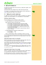
5.1 Setting the module’s addresses
Any
ADwin-Pro
module (except CPU modules) is addressed in an
ADbasic
program via its module address. The module address is free selectable.
Selecting a module’s address
Note the following rules for selecting a module’s address:
– A module address mut be unique inside its module group.
Each module is member of a module group:
• Pro I modules, functional group CPU: processor modules.
• Pro I modules, functional group ADC: analog input modules.
• Pro I modules, functional group DAC: analog output modules.
• Pro I modules, functional group DIO: digital input/output modules,
relays and counter modules.
• Pro I modules, functional group EXT: special modules of all kind.
• All Pro II modules.
– A module address must be within the following limits:
• Pro I modules: 1 … 255.
• Pro II modules: 1 … 15.
There are special limits for RSxxx- and fieldbus modules (see below)
It is true that you can select the same module address for modules of different
groups. Nevertheless we recommend to use unique adresses in order to pre-
vent a mix-up.
Setting the module’s adress: Pro II modules
With Pro II modules you set the module address with the program
ADpro
. Set-
tin the address also resets the Pro modules to initial state.
Switch off the power supply of the
ADwin
system and insert the Pro II modules
into the casing; please note the description on
. Power up the
ADwin
system again.
Afterwards you start the program
ADpro
from the Windows Start menu under
Programs
ADwin
. Select the module address with the menu entry
Edit
Set
module
adresses
.
Setting the module’s adress: Pro I modules
With Pro I modules you set the module address manually via DIP-switches.
The on-board block of DIP-switches is located right to the bottom.
Wit 8 DIP switches the address is selectable between 1 and 255 (see
Each module of the same group needs to have a different address.


