Pro I: Analog Input and Output Modules
Pro-AO-16/8-12 Rev. A
ADwin
90
ADwin-Pro
Hardware, manual version 2.9, June 2006
5.7 Pro I: Analog Input and Output Modules
5.7.1 Pro-AO-16/8-12 Rev. A
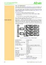
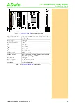
The analog input/output module
includes a ADC
(12 bit) with 16 multiplexed channels and 8 DAC (12 bit). The outputs are
equipped with a fixed 1
st
order low-pass filter (f
c
=100kHz) to cut off glitches.
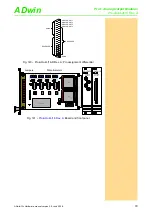
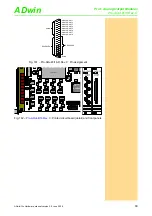
The 16 inputs and 8 outputs are connected with a 37-pin DSUB connector.
The voltage ranges of the ADC and DAC can be set by 3 jumpers and adjusted
by potentiometers (see
).
This module has an address in the group of the analog input modules as well
as in the group of the analog output modules.
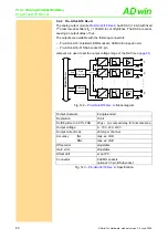
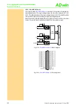
: Block diagram
Fig. 164 –
: Pin assignment
Data
AD
w
in
-P
ro
bus
A
D
1
100k
100k
100k
. . . . . . .
Addr.
Data
Data
Register
Address
Decoder
Data
PGA
Vu= 1, 2, 4, 8
. . . . . . .
MUX
2
ADwi
n
-P
ro
bus
Addr.
Data
Data
Register
Address
Decoder
InAmp
+
-
1
8
LPF
InAmp
+
-
LPF
InAmp
+
-
LPF
. . . . .
. . . . .
. . . . .
D
A
D
A
D
A
D
A
D
A
D
A
D
A
D
A
...
..
2
16
GND
AGND
AGND
AGND
AGND
AGND
AGND
AGND
AGND
ANALOG IN 9
ANALOG IN 10
ANALOG IN 11
ANALOG IN 12
ANALOG IN 13
ANALOG IN 14
ANALOG IN 15
ANALOG IN 16
AGND
RESERVED
ANALOG OUT 1
ANALOG OUT 2
ANALOG OUT 3
ANALOG OUT 4
ANALOG OUT 5
ANALOG OUT 6
ANALOG OUT 7
ANALOG OUT 8
ANALOG IN 1
ANALOG IN 2
ANALOG IN 3
ANALOG IN 4
ANALOG IN 5
ANALOG IN 6
ANALOG IN 7
ANALOG IN 8
AGND
RESERVED
DGND
19
18
17
16
15
14
13
12
11
10
9
8
7
6
5
4
3
2
1
37
36
35
34
33
32
31
30
29
28
27
26
25
24
23
22
21
20


