background image

AM-800CL / AB-800CL 

- 54 - 


Tool is connected to a camera and the camera is turned on.   

10.2.2      Communication Window 

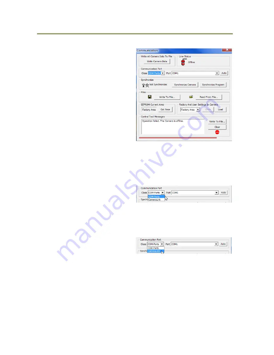
The Communication Window is used to connect 
the  Camera  Control  Tool  with  the  JAI  camera. 
Depending  on  the  camera  there  are  2  possible 
ways to communicate with a JAI camera.     
 

RS-232C 

Select the communication port, where the serial 
cable  is  connected  from  the  list  box  in  the 
„Communication  Port‟  field,  or  click  the  „Auto‟ 
button to search for a camera on communication 
port  1  to  16.  The  camera  control  program 
automatically sends a camera request on every 
communication  port.  The  user  is  prompted  to 
use  a  communication  port  if  a  camera  answers 
the request. 


RS-232C and Camera Link 

The  Communication  Window  looks  a  bit  different  when  it  is  possible  to  communicate  with  the 
camera using Camera Link and RS-232 com port. The Communication area contains 2 list boxes now. 

 
RS-232CCommunication 


1. Select ‟COM-ports‟ from the ‟CL 
Manufacturer/COM-ports‟ list Box.   


2. Select the communication port, where 
the serial cable is connected to the 
camera from the ‟Serial Port‟ list box or click the „Auto‟ button to search for a camera on 
communication port 1 to 16.   


The  Serial  Port  list  box  and  the  Auto  search  button  are  only  active  when  COM-ports  is 
selected

.


Camera Link communication 

The  ‟CL  Manufacturer/COM-ports‟  list  box  also 
contains  DLL  file  names  (or  frame  grabber 
names) for all Camera Link frame grabbers that 
are  installed  in  the  pc.  This  is  done  by  using  a  DLL  file  called  "clserial.dll"  to  upload  all  frame 
grabber DLLs that are found in the pc.   
Just select the option for the frame grabber that is installed in the pc

.   


Auto Search 

Click the auto button to search for a camera on communication port 1 to 16. The camera control 
program automatically sends a camera request on every communication port. The user is prompted 
to use a communication port if a camera answers the request.   
This button is only used for RS-232 communication.   


Summary of Contents for AM-800CL

Page 1: ...1027E 1102 AM 800CL AB 800CL 8M Digital Progressive Scan Monochrome and color Camera Document Version ver 1 5 AMAB 800CL_Ver 1 5_Sept 2011 User Manual...

Page 2: ...1 FCC This equipment has been tested and found to comply with the limits for a Class B digital device pursuant to Part 15 of the FCC Rules These limits are designed to provide reasonable protection ag...

Page 3: ...asures for the Administration of the control of Pollution by Electronic Information Products known as China RoHS The table shows contained Hazardous Substances in this camera mark shows that the envir...

Page 4: ...asures for the Administration of the control of Pollution by Electronic Information Products known as China RoHS The table shows contained Hazardous Substances in this camera mark shows that the envir...

Page 5: ...ate calculation if AOI is set 17 5 4 2 2 If the bit allocation is set to 8 10 or 12bit and the binning is OFF or 2x1 18 5 4 2 3 If the bit allocation is set to 8 10 or 12bit and the binning is 1x2 or...

Page 6: ...eadout 35 7 8 Edge dump mode so called RCT 36 7 9 PIV Particle Image Velocimetry 37 7 10 Operation and function matrix 37 8 Other functions 38 8 1 Black level control Command BL 38 8 2 Gain control Re...

Page 7: ...ns table 61 Appendix 63 1 Precautions 63 2 Typical Sensor Characteristics 63 3 Caution when mounting a lens on the camera 63 4 Caution when mounting the camera 64 5 Exportation 64 6 References 64 Manu...

Page 8: ...resolution and high frame rate cameras with 3296 h x 2472 v pixel resolution and a 17fps frame rate for monochrome and Bayer color Accordingly the amount of data produced is very large If the output...

Page 9: ...tion control together with timed trigger width and trigger controlled exposure controls Both cameras also have edge dump and PIV modes The AM 800CL has H and V binning modes and both the AM 800CL and...

Page 10: ...hrome and Bayer or 8 bit output RGB color 17 frames second with full resolution in continuous operation for monochrome or Bayer output 8 5 frames second for AB 800CL RGB output in camera interpolation...

Page 11: ...e Rear protrusion on C mount lens must be less than 10 0mm 2 Note When a Camera Link cable is connected to the camera please do not excessively tighten screws by using a driver The Camera Link recepta...

Page 12: ...sion on F mount lens must be less than 12 0mm 2 Note When a Camera Link cable is connected to the camera please do not excessively tighten screws by using a driver The Camera Link receptacle on the ca...

Page 13: ...ower connected initiating Steady green Camera is operating in Continuous mode Flashing green The camera is receiving external triggering Note The interval of flashing does not correspond with external...

Page 14: ...y internal switch setting The default is the complementary emitter follower circuit See chapter 5 1 3 for the details 2 Factory default is trigger via Camera Link 5 1 2 Camera Link connector 5 1 2 1 F...

Page 15: ...24 N C 12 25 N C 13 26 Shield GND 5 1 3 DIP switch SW500 The XEEN output through HIROSE 12 pin 9 can be connected to the complementary emitter follower circuit or the open collector circuit DIP switc...

Page 16: ...B7 TAP B11 G7 Tx11 Port C0 TAP B0 TAP B0 B0 Tx15 Port C1 TAP B1 TAP B1 B1 Tx18 Port C2 TAP B2 TAP B2 B2 Tx19 Port C3 TAP B3 TAP B3 B3 Tx20 Port C4 TAP B4 TAP B4 B4 Tx21 Port C5 TAP B5 TAP B5 B5 Tx22 P...

Page 17: ...EN output XEEN is on pin 9 of the 12 pin Hirose connector The output uses either a complementary emitter follower circuit or open collector The output of the complementary emitter follower circuit is...

Page 18: ...nk output The AM 800CL and AB 800CL have a 4 tap readout from the CCD The 4 tap output is combined horizontally to output 2 taps through the Camera Link interface Fig 12 2 tap output In the case of RG...

Page 19: ...the frame rate setting should use fewer lines that that of AOI height For AOI setting if the upper TAP and lower TAP have the same duration the fastest frame rate can be achieved Thus if the AOI is c...

Page 20: ...ght 26 Frame lines number Frame rate Hz 1 Frame lines number x 0 00004655 5 4 2 3 If the bit allocation is set to 8 10 or 12bit and the binning control is 1x2 or 2x2 Note In this case offset and heigh...

Page 21: ...y Hz 0 2472 1263 17 01 Upper TAP 0 1236 1263 17 01 Center 618 1236 799 26 89 Lower TAP 1236 1236 1262 17 02 Upper TAP upper 0 618 800 26 85 Upper TAP lower 616 618 800 26 85 Center 926 618 568 37 82 L...

Page 22: ...ower 1852 618 484 40 87 Upper TAP upper 0 310 408 48 49 Upper TAP lower 924 310 408 48 49 Center 1080 310 368 53 76 Lower TAP upper 1236 310 407 48 61 Lower TAP lower 2160 310 407 48 61 Upper TAP uppe...

Page 23: ...hand the resolution becomes less than the full frame readout H x V Pixels Sensitivity Spatial resolution H direction V direction 1 x 2 2 times Unchanged 1 2 2 x 1 2 times 1 2 Unchanged 2 x 2 4 times...

Page 24: ...Sensor layout 6 2 Vertical timing 8bit 10 bit or 12bit for Bit allocation 6 2 1 If the binning control is BNC 0 OFF or BNC 2 2x1 6 2 1 1 AOI default setting Offset 0 Height 2472 Frame rate 1263L 17 0...

Page 25: ...L Frame rate Hz 618 1236 181 618 0 799 26 89 927 618 258 309 0 567 37 89 309 618 104 618 78 800 26 85 463 309 142 309 116 567 37 89 6 2 2 If the binning control is BNC 1 1x2 or BNC 3 2x2 6 2 2 1 AOI i...

Page 26: ...ing Vertical binning AOI setting LVAL FVAL DVAL DATA EEN XEEN CCD Expsoure Valid data A B C 3L Offset HEGHT A L B L C L Total line L Frame rate Hz 618 1236 175 309 0 484 40 87 926 618 98 309 0 407 48...

Page 27: ...setting Fig 24 Vertical timing RGB output mode AOI setting Offse t HEGHT A L B L C L Total line L Frame rate Hz 412 1648 130 1648 123 1901 11 30 618 1236 181 1236 175 1592 13 49 928 618 259 618 252 11...

Page 28: ...1clk 25ns via Camera Link Exposure starting line 1LVAL 4364 clk 54 55 s Fig 26 Horizontal timing Vertical binning ON 6 4 3 DVAL output if the Binning control is set to 2 2x1or 3 2x2 If the Binning con...

Page 29: ...sure start OFF 2x1 380clk 620clk 3724clk 46 55 s 3964clk 49 55 s 1x2 2x2 700clk 1020clk 4044clk 50 55 s 4364clk 54 55 s Fig 28 LVAL LOW period varies 2 When the trigger control mode is set to ON and O...

Page 30: ...F the frame rate can be set longer than 1 frame the normal period needed to capture all pixels By doing this the sensitivity of the image can be increased Maximum recommended exposure time is 2 second...

Page 31: ...is effective only when the trigger mode is ON the exposure mode is set to Timed and the exposure sequence is ON 7 3 Trigger Control 7 3 1 Selection of the trigger input Command TI The command TI can s...

Page 32: ...rates the same as RCT mode If this mode is enabled Until the trigger is input the camera operates continuously and the video signal for the auto iris lens is output When the trigger is input the fast...

Page 33: ...posure settings Exposure mode EM 1 Exposure time PE 10 s 2000000 s or Select Auto shutter control ASC Exposure time auto ASC 1 ON Exposure time auto speed ASCS 1 16 Deafult is 8 Exposure time auto max...

Page 34: ...r control Trigger mode TM 1 ON Trigger overlap TO 0 OFF or 1 Readout OFF LVALsync Readout LVALsync async automatic setting Trigger source TI 0 Camera Link default or 1 Hirose 12 pin Trigger Activation...

Page 35: ...rigger input Binning Control t Trigger is input during CCD readout Sync OFF 2x1 53 s 25ns 1x2 2x2 61 s 25ns Trigger is while CCD readout is not activated Async 6 56 s 25ns Fig 31 Readout Trigger LVAL...

Page 36: ...42964 Exposure control Exposure mode EM 2 Trigger width Trigger control Trigger mode TM 1 ON Trigger overlap TO 0 OFF or 1 Readout OFF LVALsync Readout LVALsync async automatic setting Trigger source...

Page 37: ...igger input Binning Control t1 t2 Trigger is input during CCD readout Sync OFF 2x1 53 s 25ns 83 2 s 25ns 1x2 2x2 61 s 25ns 87 2 s 25ns Trigger is while CCD readout is not activated Async 6 56 s 25ns 3...

Page 38: ...for full pixels readout is AM 800CL is 17 0263fps Fast dump period Exposure time AB 800CL is 8 5fps Fast dump period Exposure time Primary settings to use this mode Acquisition control Acquisition fra...

Page 39: ...wo video outputs The frame rate for full pixels readout is 8 5fps for both AM 800CL and AB 800CL Primary Settings Exposure mode Timed PIV control ON Trigger mode TM 1 ON Fig 35 PIV mode 7 10 Operation...

Page 40: ...JUT1 GJUT2 GJUT3 The Tap control function adjusts automatically or manually the OFFSET and the gain differences between the upper and lower taps and the right and left taps The sensor used in the AM 8...

Page 41: ...only in continuous mode or edge dump mode 8 5 Auto white balance Related commands AWB PGS PGR PGGR PGGB PGB In this function the gain of each R Gr Gb and B color can be individually adjusted to get th...

Page 42: ...he factory and can be turned ON or OFF The default setting is OFF Fig 39 Blemish compensation Note If defective pixels are found consecutively in the horizontal direction the blemish compensation circ...

Page 43: ...ge and use that data as the reference Luminance levels of other areas are then adjusted so that the level of the entire area is equal The block for compensation is 64 pixels x 64 pixels and the comple...

Page 44: ...tputs as a monochrome signal The Bayer color interpolation can complement lacking color information on each pixel and output RGB color data as the result Color interpolation compensates for the lack o...

Page 45: ...This function reads out the temperature inside the camera The measuring range 55 to 125 C Resolution 0 0625 C The following table shows examples of values which can be read out by the TMPO command The...

Page 46: ...camera answers NN Parameter CR LF Transmit the following to have the camera s actual settings ST CR LF The camera answers A complete list of the current settings Transmit the following to have a comm...

Page 47: ...ettings and utility commands 1 Camera Status Request ST CR LF Actual setting 2 Online Help Request HP CR LF Command list 3 Firmware Version VN CR LF 3 digits e g 100 Version 1 00 4 Camera ID Request I...

Page 48: ...3 Trigger Activation TA Param CR LF TA CR LF 0 Rising edge 1 Falling edge If EM 2 0 High 1 Low 4 Trigger overlap TO Param CR LF TO CR LF 0 off 1 Read out F Exposure control 1 Exposure Mode EM Param CR...

Page 49: ...um gain value AGCGA Param CR L F AGCGA CR LF 0 to 672 AM 800CL 84 to 672 AB 800CL 7 Gain Auto Minimal gain value AGCGI Param CR LF AGCGI CR LF 84 to 588 AM 800CL 0 to 588 AB 800CL 8 Black Level BL Par...

Page 50: ...a is 512 Param 0 to 8191 After sending consecutive 512 data LUT data can be renewed J Gain and black level for TAP balance 1 Gain auto Tap Balance AWA Param CR LF 0 OFF 1 Once Run 2 Continuous 2 Reque...

Page 51: ...balance BBRS CR LF 0 Complete 1 Too Bright 2 Too dark 3 Timeout Error 4 Busy 5 Limit 6 Trig is not set as Normal 14 Fine Black for tap 2 BL2 Param CR LF BL2 CR LF 512 to 511 Tap2 Black Fine For User...

Page 52: ...h BMRC Param CR LF Param 2 White 3 Blemish Threshold White BMTHW Param CR L F BMTHW CR LF 0 to 16383 4 BLMP White H BMWH Param1 Param2 CR LF BMH Param1 CR LF Param1 Blemish No 1 to 256 Param2 H positi...

Page 53: ...posure Sequence EXSQ Param CR LF EXSQ CR LF 0 OFF 1 ON Available when EM 1 2 2 Exposure Sequence No N 1 16 PES N Param CR LF PES N CR LF 0 15 3 Exposure Repeat Time N 1 16 PER N Param CR LF PER N CR L...

Page 54: ...ble when EXSQ 1 17 Exposure time 12 PE12 Param CR LF PE12 CR LF 10 s 2000000 s Available when EXSQ 1 18 Exposure time 13 PE13 Param CR LF PE13 CR LF 10 s 2000000 s Available when EXSQ 1 19 Exposure ti...

Page 55: ...When the program is started the last settings for the program are loaded from the file CameraName ini 10 2 Camera Control Tool interface The Camera Control software consists of the main tool bar and a...

Page 56: ...oxes now RS 232CCommunication 1 Select COM ports from the CL Manufacturer COM ports list Box 2 Select the communication port where the serial cable is connected to the camera from the Serial Port list...

Page 57: ...ettings from the camera to the program Files When clicking the Write to File or Read from File button the user is prompted for a file using a standard file dialog New files are created if they do not...

Page 58: ...AM 800CL AB 800CL 56 10 2 3 Camera Control Window 10 2 3 1 Exposure Control 10 2 3 2 Gain Control...

Page 59: ...AM 800CL AB 800CL 57 10 2 3 3 Blemish Control When Open LUT table is clicked the left side window will open for example for blue channel...

Page 60: ...4 7 1 42 36 0 55 0 28 1 42 36 40 1 57 1 57 1 57 40 40 69 45 45 45 62 2 44 3 0 12 30 1 18 55 2 17 27 5 55 2 17 27 5 1 08 1 08 depth0 18 depth0 18 depth0 18 depth0 18 POWER TRIG DIGITAL I O DC IN TRIG P...

Page 61: ...O POWER TRIG 2 17 F Mount F Mount F Mount 55 27 5 1 08 55 2 17 27 5 1 08 1 77 1 77 14 0 55 40 1 57 1 57 40 45 45 50 1 97 36 1 42 62 2 44 3 0 12 1 77 1 57 40 45 16 0 630 12 0 472 57 41 1 61 2 24 98 1...

Page 62: ...AM 800CL AB 800CL 60 12 Specifications 12 1 Spectral response Fig 41 Spectral response AM 800CL Fig 42 Spectral response AB 800CL...

Page 63: ...te number of horizontal pixels cannot be changed Sensitivity on sensor minimum 0 04 Lux Max gain Shutter OFF 50 video 3200K IR Cut CM500S 0 06 Lux Max gain Shutter OFF 50 Green 4600K S N ratio More th...

Page 64: ...ower DC 12V to 24V 10 7 8W at normal operation DC 12V Lens mount C mount or F mount The rear protrusion on C mount lens must be less than 10mm The rear protrusion on F mount lens must be less than 12m...

Page 65: ...shes Over time some pixel defects can occur This does not have a practical effect on the operation of the camera These will show up as white spots blemishes Exposure to cosmic rays can cause blemishes...

Page 66: ...pod mounting plate please use the provided screws 5 Exportation When exporting this product please follow the export regulation of your own country 6 References 1 This manual can and datasheet for AM...

Page 67: ...table on 7 6 2 and 7 7 2 April 2011 Ver 1 2 Correct sensitivity specifications Correct Protocol table May 2011 Ver 1 3 5 4 1 2 CameraLink out put drawing modified 7 3 2 and 7 7 Trigger activation for...

Page 68: ...manual are trademarks or registered trademarks of their respective owners JAI A S cannot be held responsible for any technical or typographical errors and reserves the right to make changes to product...

Reviews: