EN Camera Series
50
Camera Features
6.7.2
JPEG Format
JPEG is the industry-standard format for lossy image compression. Output file size, quality and
speed of the encoding depends on the quality setting. The user can set the proper quality setting by
accessing the "JPEG Quality Factor" config register (Address = 46). The factory default is 85.
Access to “Image Acquisition 1” and “Image Acquisition 2” config registers (Address = 3 and 9,
respectively) and turn on JPEG format. Factory default setting is TIF format only.
If JPEG quality factor is high (above 85) and image contains complex detail information, the output
file size of JPEG encoding becomes larger. JPEG image size must be properly defined in “Storage
Setup” of JPEG. If the output file size exceeds the pr defined JPEG image size, the result JPEG
image will not contain the full resolution of the image. Please refer to Section 6.9, “Image
Buffering,” on page 44).
For the EN Camera (color) model, the user should not deal only with the JPEG format image,
because this format will not retain detailed color pixel information.
Please refer to the “LC to EN Interface” document for details about the JPEG header.
6.8
Image Transfer
6.8.1
UDP Image Transfer on Setup Channel
The EN camera can send video images over TCP (message-based) on the control channel, or UDP
(sniffing mode) on the setup channel, or both. Image transfer over UDP is intended for live video
display to focus lens or for sniffing external triggers (HW TTL trigger, Ethernet Trigger, or RS485
Serial Trigger) without disturbing continuous normal operation with Lane Controller. The “Live” or
“Snap” buttons on the UDP setup channel do not send images to the FTP server or the lane
controller on TCP (message-based) image transfer. Half image and quarter images are supported
only on the UDP setup channel. The raw image format is the only one supported by the UDP setup
channel; JPEG is not supported.
UDP setup images are easy to enable and disable. The user can access the “EN Setup Trigger
Source” register (Address = 111) and “EN Setup Image size” register (Address = 112) to change the
trigger source and image size. Live image transfer can be slowed down by setting “EN Setup UDP
Inter-Packet Delay” register (Address = 110). It is important to note that when multiple host PCs
(clients) connect to the EN camera, only the last client who changes the “EN Setup Trigger Source”
register or “EN Setup Image size” register will receive the UDP setup image.
6.8.2
TCP Message-Based Image Transfer on the Control Channel
Image transfer over TCP is intended for more secure image transfer. Even if the packet is corrupt,
the TCP/IP mechanism automatically resends the missing/corrupt packets. Full size, Odd field, or
Even field images are supported and both raw TIF images and compressed JPEG images are
supported on TCP control channel.
Unlike the setup channel that can send only one uni-cast UDP image to a single client (host PC), the
control channel can send the identical image to multiple host PCs (clients) over TCP. However, the
host PC has to respond to “DATA_RDY” message that the EN camera sends when an external trigger
is input (HW TTL trigger, Ethernet trigger, or RS-485 trigger). If the host PC sends a “SEND_DATA”
message to the EN camera, then the EN camera sends TCP image (TIF, or JPEG, or both) over the
Control channel.
For detailed register and interface information, please refer to the “EN to LC Interface” document.
As a default, the EN setup software receives all images over UDP (setup channel). However, if you
prefer to switch to TCP images, you can do so by enabling the "Use TCP/IP" option. This is under the
"View" menu on the Video Window.
Summary of Contents for EN Series Cameras TS(C)-1327EN
Page 2: ......
Page 8: ...EN Camera Series viii List of Figures ...
Page 10: ...EN Camera Series x List of Tables ...
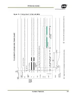
Page 39: ...Camera Features 39 EN Camera Series Figure 15 Timing Chart 1 TS C 2030EN ...
Page 40: ...EN Camera Series 40 Camera Features Figure 16 Timing Chart 2 TS C 1327EN ...
Page 41: ...Camera Features 41 EN Camera Series Figure 17 Timing Chart 3 TS C 4032EN ...
Page 67: ......


