background image

38


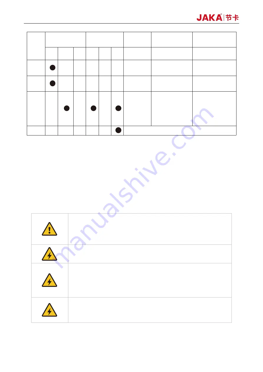
Verification

number

Inspection cycle

Maintenance

Inspecting

Parts

Inspecting Content

Inspection/process

ing method

Daily

Every 3

months

Every 1

year

4 year 5 year 8 year

1

Surfaces

Whether there is

splashes, dust, etc.

Visual confirmation,

cleaning

2

Filters

Whether there is dirt or
blockage

Visual confirmation,

cleaning, replacement

3

Cables

Confirm whether there
is any damage or
fragmentation
•Confirm whether the

connectors are loosed.

Visual confirmation,

tightening. Replace the

cable when it is

obviously damaged.

4

Overhaul

(P.S.) Use a soft cloth to remove dusts when cleaning. Do not blow off dust with equipment such as air

blowers. Wind pressure will cause the dusts to enter the inside of the fan and the blades rotate at a speed
exceeding the rated speed, which may cause the fan to malfunction or affect its life. Only use the vacuum
cleaner on the blade section. Do not vacuum the rotating part or the main body, which can cause the fan to
malfunction or reduction of the fan’s service life.

5.3 Parts Replacement and Preservation

When replacing the parts of the robot control unit, please observe the following precautions and work

safely.

1

Do not carry out any modification of our products.

2

Fire, malfunction, and wrong movements caused by modification may result

in personal injury or damage to the robot.

3

Any loss caused by the user's own modification of JAKA's products is not

covered by JAKA’s warranty.

1

To prevent electric shock, when replacing parts, please turn off the circuit

breaker, and then turn off the main power supply.

1. Turn off the main power, wait for 5 minutes, and then the parts could be

replaced if needed.

2. There is a risk of electric shock, due to residual charge in the electronic

components.

3. Do not use wet hands for work.

4. In case of electric shock, it will result in serious injury or death.

1. 1.The replacement must be carried out by the specified operator.

2. 2.Electric shock or being caught by a robot accidentally can result in serious

injury or death.

JAKAZu 5

Summary of Contents for Zu pro Series

Page 1: ...JAKA ROBOTICS User Manual Hardware This manual also applies to Zu pro series JAKA Zu 5...

Page 2: ...JAKA ROBOTICS User Manual Robot Serial Number Cabinet Serial Number JAKA Zu 5...

Page 3: ...her users of JAKA robots must be familiar with JAKA robot programming and system integration IP class of Zu series is IP54 IP class of Zu pro series is IP65 How to Read This Manual This manual mainly...

Page 4: ...IEW OF ROBOT CONFIGURATIONS 11 2 2 OPERATION TERMINAL 11 2 3 ROBOT ARM 12 2 3 1 Robot End 12 2 3 2 Flange Buttons and interfaces 13 2 4 ELECTRICAL CABINET AND CONTROL STICK 14 3 MECHANICAL SPECIFICATI...

Page 5: ...OOL INPUT AND OUTPUT 33 4 5 1TIO function description 33 4 6 TECHNICAL SPECIFICATIONS 35 5 MAINTENANCE AND REPAIR 37 5 1 SAFETY INSTRUCTIONS 37 5 3 1 Filter cleaning and replacement 40 5 3 2 Part pres...

Page 6: ...n efficiency What Do the Boxes Contain Item Amount Robot 1 Electrical cabinet 1 Key to cabinet 1 Power Supply Cable 1 JAKA Certificate of Quality 1 User Manual 1 Warranty Card 1 JAKAZu 5 is at your se...

Page 7: ...ch if touched could result in injury 1 3 Safety Precautions This section is mainly for the protection of operators and related matters that need to be paid attention to during the first installation U...

Page 8: ...Combining different machines might increase hazards or create new hazards Always make an overall risk assessment for the complete installation 7 Never modify the robot A modification might create haza...

Page 9: ...t the operator can understand the working range of the robot with the end effector gripper tool etc mounted 5 Make sure that safety measures and or robot safety configuration parameters have been set...

Page 10: ...is includes but is not limited to the following Use in potentially explosive environments Use in medical and life critical applications Use before performing a risk assessment Use where the rated perf...

Page 11: ...mage the joints 2 If the brake is released manually gravitational pull can cause the robot arm to fall Always support the robot arm tool and work item when releasing the brake 1 9 Precautions for Tran...

Page 12: ...s and software usages please refer to other chapters During using of JAKA Zu robots if quick help is needed feel to free to call our hotline 86 400 006 2665 As shown in Fig 2 1 JAKA Zu robots uses wir...

Page 13: ...ot arm is shown as Fig 2 1 and is composed of six rotation joints with two linkages And at the end of the arm a ring indicator buttons used to drag and tech TIO interface are located Fig 2 1 Robot Arm...

Page 14: ...should be evaluated carefully the contact of robot and personnel could cause server injury of personnel or damage of equipment 2 3 2 Flange Buttons and interfaces On the side of flange located two bu...

Page 15: ...ands can be sent to the robot using buttons on the stick and are described as follows table 2 3 Stick Function Description ON OFF ON Press the power button for 1 second and release it The buzzer will...

Page 16: ...he lock indicator light will be orange Unlock handle Press and hold the lock button for 3 seconds and the lock indicator light will go out Combination function Other buttons and lock button can be pre...

Page 17: ...ig3 1 The base is used to install the robot and the tool end is used to mount the tool The tool can perform translational and rotational movements in the robot s working range The following sections d...

Page 18: ...d electrical cabinet are shown in Fig 3 2 and Fig3 3 Make sure to take into account the working range of the robot during installation to avoid injury to people or damage to the equipment 3 1 2 Robot...

Page 19: ...ecause it causes the joints to move fast even though the tool is moving slowly causing the robot to work inefficiently and making it difficult to conduct a risk assessment Fig3 4 3 2 Installation 3 2...

Page 20: ...in water or in a wet environment 3 2 3 Robot Body Installation The robot has an attitude and position adaptation function It can be mounted in various ways such as ground wall and celling mounting As...

Page 21: ...flange has four M6 tapped holes to mount the end effector When screws are installed in these threaded holes the screws need to be tightened with a torque of 15 Nm If you need to adjust the tool posit...

Page 22: ...e safety interface signal from the normal I O interface signal 2 All safety signals are redundant two independent channels Keeping the two channels independent ensures that no safety features are lost...

Page 23: ...le after extended testing and shielded cables are required if necessary 4 3 Front panel of the electrical cabinet The front panel interface of the electrical cabinet is arranged on the first floor aft...

Page 24: ...l output PNP Type 1A continuous current output capability 6 DO6 6th digital output PNP Type 1A continuous current output capability 7 DO7 7th digital output PNP Type 1A continuous current output capab...

Page 25: ...tive encoder A 4 5 2P Differential signal 2 input positive encoder B 12 13 2N Differential signal 2 input negative encoder B 6 7 3P Differential signal 3 input positive encoder Z 10 11 3N Differential...

Page 26: ...ivided into V power selection security I O configuration The electrical cabinet supports 16 digital inputs and 16 digital outputs as shown in Figure 4 2 Figure 4 2 The digital I O can be powered by a...

Page 27: ...2 and SI1 2 are both connected to V V is connected to 24V and V is connected to 0V it indicates that 24V power is provided inside the electrical cabinet As shown in Figure 4 4 Figure 4 4 2 Connect the...

Page 28: ...Protective stop function support automatic recovery The electrical cabinet door switch is an application case of the protection stop device and the robot stops when the electrical cabinet door is open...

Page 29: ...ult uses internal 24V power supply The high level range is 15 24V and the low level range is 0 11V Users can also connect DIx to V directly Different types of input signals have different connections...

Page 30: ...terface is changed 4 3 3 Digital Output DO Figure 4 11 The electric control cabinet has 16 channels PNP type output interface DO1 DO16 to support isolated signal output The digital output uses a high...

Page 31: ...lectrical cabinet has 2 analog input and output interfaces Ch1 Ch2 the input mode can be configured and the AI mode is as follows 1 Current signal input 4 to 20 mA 2 Voltage signal input 0 5V 0 10V 10...

Page 32: ...12V power supply or VSB interface through the switch 4 3 7 Safety I O In order to ensure the safety function configuration of the robot the electrical cabinet provides two fixed safety function input...

Page 33: ...is configured to be 10A at the factory The power source used by the robot should be equipped with at least grounding mains fuse Residual current circuit breaker It is recommended to install a power sw...

Page 34: ...e customer needs to choose the TIO external cable please call 400 006 2665 Figure 4 17 shows the cable specifications Figure 4 17 Cable specifications 4 5 1 TIO function description The TIO interface...

Page 35: ...gray GND 24V Power Ground 1 TIO analog input interface Analog input AI1 supports 10V 10V high precision voltage range input 2 TIO digital input interface The digital input uses the optocoupler cathod...

Page 36: ...such as a relay electromagnet DC motor etc requires an external freewheeling diode Figure 4 21 Note It is strongly recommended to use protection DIODES for the inductive loads such as relays electrom...

Page 37: ...ature 0 50 C IP classification IP54 Robot installation posture Install at any angle TIO Ports 2 digital input 2 digital output 1 analog input TIO Power 24V Base diameter 158mm Material Aluminum alloy...

Page 38: ...robot system shall be considered as a new system which means that the overall safety approval process including risk assessment shall be updated accordingly 2 Replace faulty components using new comp...

Page 39: ...spatter ash dust cutting residue etc All Parts Main bolts All the bolts exposed on the outside of the robot need to be tightened and marked see the specified tightening torque table including the tool...

Page 40: ...art or the main body which can cause the fan to malfunction or reduction of the fan s service life 5 3 Parts Replacement and Preservation When replacing the parts of the robot control unit please obse...

Page 41: ...or if any cable is caught After that reinstall the case If there is a gap it may cause dirt dust etc to enter the inside of the electrical cabinet which will cause malfunctions 5 3 1 Filter cleaning...

Page 42: ...he following situations it is not included in the free warranty and the user should pay for the cost of equipment JAKA should assist in troubleshooting as soon as possible to restore the equipment bac...

Page 43: ...with the user to confirm the charging method maintenance responsibility and maintenance method to ensure the performance fulfillment of maintenance responsibility III Service call hotline and contact...

Page 44: ...C 60204 1 2016 Safety of machinery Electrical equipment of machines Part 1 General requirements ISO 12100 2010 Safety of machinery General principles for design Risk assessment and risk reduction ISO...

Page 45: ...ts for industrial robots Part 1 Robots IEC 61000 6 2 2005 Electromagnetic compatibility EMC Part 6 2 Generic standards Immunity for industrial environments IEC 61000 6 4 2006 A1 2010 Electromagnetic c...

Page 46: ...s EN ISO 13849 1 2015 Safety of machinery Safety related parts of control systems Part 1 General principles for design EN ISO 10218 1 2011 Robots and robotic devices Safety requirements for industrial...

Page 47: ...45 Machinery Directive 2006 42 EC EN ISO 13849 1 2015 Safety of machinery Safety related parts of control systems Part 1 General principles for design JAKA Zu 5...

Page 48: ...46 Machinery Directive 2006 42 EC EN ISO 10218 1 2011 Robots and robotic devices Safety requirements for industrial robots Part 1 Robots JAKAZu 5...

Page 49: ...ustrial environments EN 61000 6 2 2005 Electromagnetic compatibility EMC Part 6 2 Generic standards Immunity for industrial environments The company s product JAKA Zu5 robot has passed the EU CE EMC d...

Page 50: ...ery Electrical equipment of machines Part 1 General requirements EN ISO 12100 2010 Safety of machinery General principles for design Risk assessment and risk reduction The company s product JAKA Zu 5...

Page 51: ...t passed the European Union RoHS 2 0 2011 65 EU and Amendment Directive EU 2015 863 and complies with the European Union RoHS 2 0 2011 65 EU and Amendment Directive EU 2015 863 The relevant requiremen...

Page 52: ...50 7 Warranty 7 1 Product Warranty JAKAZu 5...

Page 53: ...ed to JAKA shall vest in JAKA The ownership of equipment or components replaced or returned to JAKA belongs to JAKA Any other claims resulting out of or in connection with the device shall be excluded...

Page 54: ...52 Shanghai JAKA Robotics Ltd Add Building 33 35 No 610 Jianchuan Road Minhang District Tel 400 006 2665 Web www jaka com JAKAZu 5...

Reviews: