Version: 3.1.0
15
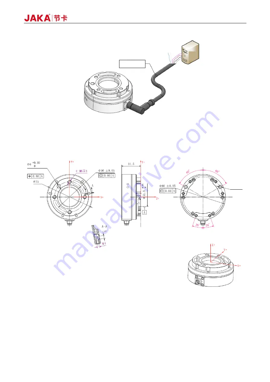
Figure 2-5 Electrical Connection of the Sensor
2.1.2.2 Sensor Installation
The mounting holes and dimensions of the sensor are shown in Figure 2-6.
Figure 2-6 Sensor Dimensions
The sensor installation procedure is as follows:
a.
Please ensure that the surfaces of the robot end, mounting flange and sensor are free of damage or
foreign objects. If the contact is non-uniform due to factors such as the inclusion of foreign objects,
gaps will be formed between them. As a result, the product may not meet IP64 compliance and would
have reduced output quality.
Multicore cable
Power supply
Data communication
Terminal
device
Pin hole
Load reference
plane
Pin hole
2-
∅
5, depth 6
Summary of Contents for Zu Series
Page 1: ...JAKA ROBOTICS Force Control Products JAKA Se and JAKA Sp...
Page 3: ......
Page 4: ......
Page 17: ...Version 3 1 0 13 M3 2 0 M4 4 0 M5 8 0 M6 13 0 M8 35 0...
Page 41: ...Version 3 1 0 37 Figure 2 36 Installation and Dimensions of the Force Sensor Indicator light...
Page 61: ...Version 3 1 0 57 Figure 3 8 Force Display Interface of the App...
Page 75: ...Version 3 1 0 71 Figure 3 19 Force Display Interface of the App...
Page 79: ...Version 3 1 0 75 Figure 3 21 Collision Detection Function Settings of JAKA Zu Sp...


