18
Force Control Products
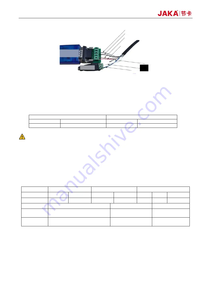
Figure 2-11 Wiring of the 422/485-USB Adapter and Power Plug
Note: This sensor requires a 24V DC power supply from the internal power of the CAB or an additional power
source. The DC power plug shown in Figure 2-11 is only for illustration purposes and is not provided with the
product. Please prepare one separately.
Indicator Light Descriptions:
Power light
Status light
Steady on
Sensor powered on
Flashing
Sensor in operation
Off
Sensor powered off
Off
Sensor idle
WARNING:
Before securing the sensor wiring harness with cable ties, be sure to check that attached peripherals do not
interfere with the robot's operational trajectory, so as to prevent the robot from pulling the wiring harness
during operation and thus causing irreversible damage to the sensor.
2.1.2.4 Sensor Specifications
The sensor specifications of type II are as follows:
Table 2-4 Sensor Specifications of Type II
Model
JK-SE-II-200
JK-SE-II-400N
JK-SE-II-H
Directions
Fx, Fy, Fz
Mx, My, Mz
Fx, Fy, Fz
Mx, My, Mz
Fx, Fy
Fz
Mx, My, Mz
Range
200N
8Nm
400N
12Nm
800N
1200N
40Nm
Overload
300% F.S.
IP Rating
IP64
Operating
Temperature
5–80°C
Power Voltage
9–24V
Accuracy
0.5% F.S.
Communication
Interface
USB
2.1.2.5 Precautions for Use
a.
Do not use in any environment with temperature or humidity beyond the allowable range.
b.
The cable must be connected properly. Before powering on the sensor, please check whether the cables
are connected according to the colors indicated in this manual. A wiring mistake could cause a shortcircuit
and damage to the internal circuit of the sensor, so do not forget to check that the wiring is correct.
c.
The sensor has built-in precision components such as embedded systems. Although we have carried
Gray
Black
Brown
Pink
Blue
Shield
White
422/485-USB
adapter
DC power plug
Summary of Contents for Zu Series
Page 1: ...JAKA ROBOTICS Force Control Products JAKA Se and JAKA Sp...
Page 3: ......
Page 4: ......
Page 17: ...Version 3 1 0 13 M3 2 0 M4 4 0 M5 8 0 M6 13 0 M8 35 0...
Page 41: ...Version 3 1 0 37 Figure 2 36 Installation and Dimensions of the Force Sensor Indicator light...
Page 61: ...Version 3 1 0 57 Figure 3 8 Force Display Interface of the App...
Page 75: ...Version 3 1 0 71 Figure 3 19 Force Display Interface of the App...
Page 79: ...Version 3 1 0 75 Figure 3 21 Collision Detection Function Settings of JAKA Zu Sp...


