background image

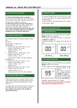
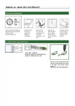
1) Use standart junction box.
Hole distance must be 60mm 
center to center.


Use 68mm hole saw.


2) Remove the
front panel 
using a thin

-

blade flat 
screwdriver.


3) Secure the
rear panel by 
screwing screws. 
Necessary 
screws are in the 
box.


4) Make the
cable connecti-
ons as shown 
below to termi-
nals on the front 
panel.


5) Attach the clip
at the top first, 
and then attach 
the clip at the 
bottom.


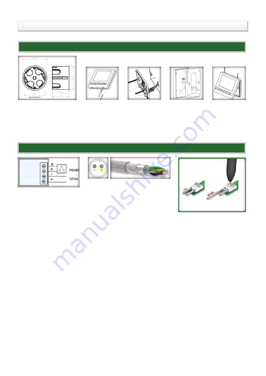
13. CONTROL PANEL CABLE CONNECTIONS

(2 x 2 x 0,34...0,75mm²)


Shielded, Twisted Pair, RS485 Data Com-
munication Cable must be used.


Note : Press the terminal buttons with 
the help of a fine

-

tipped pen as shown 

in  the  figure.  Don't  apply  extreme 
pressure.


NOTE: DON

T USE THE SCREWDRIVER


12. MOUNTING INFORMATION

MANUAL


for

 JAKKA PRO 

C

ONTROL

L

ER

Summary of Contents for Pro

Page 1: ... this appli cation Room Temperature Supply Air Temperature Outdoor Air Temperature Exhaust Air Temperature sensors can be measured by main controller Note 1 If Room Temperature Sensor is not connected to main controller Temperature Sensor value of the panel is measured Note 2 Supply Air Temperature and Room Temperature value are measured by same input If user wants to get the Supply Air Temperatur...

Page 2: ...ion if pressing FAN key for 5 seconds fan logic is changed Continious Fan Displayed as Cont on the panel Fans will work as long as the device is in the On position Default Auto Fan Displayed as Auto on the panel Fans will be active while heating or cooling In other cases the fan output is closed 7 CLOCK SETTINGS When pressing the MODE key for 6 7 seconds hour digit flashes on the panel While digit...

Page 3: ...u re 8 and Exhaust Air Temperature 2 alarm happens Electrical Heater 1 stage opens during alarm When Exhaust Air Tempe rature 2 and time passed up to the OutdoorTempFrostOutTimerLimit BMS 331 parameter alarm is eliminating 9 6 AL 06 OUTDOOR TEMP SEN FROST ALARM 9 3 AL 03 FIRE CONTACT ALARM NO If contact is in the closed position or Room Tempe rature SetFireA larmTemp BMS 343 Service Menu 44 para m...

Page 4: ... 15 C damper is open 2 Outdoor Air Temp Room Temp 3 and Setpoint Room Temp 2 and Outdoor Air Temp 35 C damper is open closed in the other conditions Cooling Mode 1 Outdoor Air Temp Room Temp 3 and Setpoint Room Temp 2 and Outdoor Air Temp 32 C damper is open 2 Outdoor Air Temp Room Temp 3 and Setpoint Room Temp 2 and Outdoor Air Temp 10 C damper is open closed in the other conditions 11 SERVICE ME...

Page 5: ...vice menu to activate the control according to the outdoor air temperature Outdoor Control Activate Firstly Main Parameter must be replaced as 9 by the MODE and FAN keys Secondly Auxiliary Para meter must be replaced as 2 by the and keys 11 6 DATE SETTINGS 1 Firstly Main Parameter must be replaced as 12 by the MODE and FAN keys Secondly Auxiliary Para meter must be set to the desired day value 2 F...

Page 6: ...ons as shown below to termi nals on the front panel 5 Attach the clip at the top first and then attach the clip at the bottom 13 CONTROL PANEL CABLE CONNECTIONS 2 x 2 x 0 34 0 75mm Shielded Twisted Pair RS485 Data Com munication Cable must be used Note Press the terminal buttons with the help of a fine tipped pen as shown in the figure Don t apply extreme pressure NOTE DON T USE THE SCREWDRIVER 12...

Reviews: