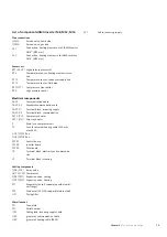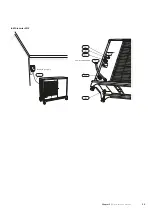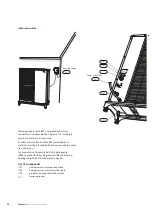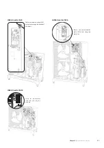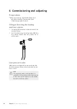
List of components
JAMA Inverter M
8,
M
12,
M
16
Pipe
connections
QM35
QM36
Service valve, liquid side
Service valve, gas side
Connection, heating medium out of
JAMA Inverter
,
XL1
G3/4" (Ø22 mm)
Connection, heating medium in to
JAMA Inverter
,
G3/4" (Ø22 mm)
XL2
Sensors
etc.
BP1
(63H1)
High pressure pressostat
Temperature sensor, heating medium return
line
BT3
Temperature sensor, condenser supply line
BT12
Temperature sensor, fluid pipe
BT15
BP2
(LPT)
Low pressure transmitter
BP4
High pressure sensor
Electrical
components
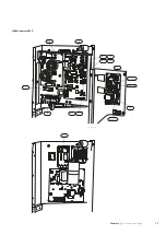
AA23
Communication board
AA23-S2
Dipswitch communication card
AA23-X1
Terminal block, incoming supply
AA23-X4
Terminal block, communication
EB10
(CH)
Compressor heater
EB11
(DH)
Drip tray heater
F
Main fuse compressor unit
Fuse for external heating cable (250 mA),
F3
max 45 W.
GQ1
(FM01)
Fan
GQ2
(FM02)
Fan
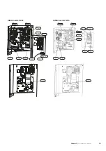
PWB1
PWB2
PWB3
Control board
Inverter board
Filter board
Terminal block, electricity and communica-
TB
tion
Terminal block incoming
X1
Cooling
components
QN2
(20S)
4-way valve
GQ10
(CM)
Compressor
QN3
(SM1)
Expansion valve, cooling
QN1
(SM2)
Expansion valve, heating
Evaporator (air coil, copper pipe with alumini-
EP1
EP2
um flange)
Condenser (ACH 30, copper/stainless steel)
Drying filter
HS1
Miscellaneous
Type plate
PF1
PF3
UB1
UB2
Serial number
Cable gland, incoming supply Cable
grommet, communication Cable
grommet, heating cable (EB14)
UB3
Cable, incoming supply
W1
15
Chapter 3 |
The heat pump design
Summary of Contents for M8
Page 1: ...Installer manual LEK LEK LEK J M Inverter M8 M12 M16 Air water heat pump...
Page 2: ......
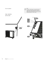
Page 16: ...LEK DATA XL2 UB1 UB2 XL1 UB3 W1 LEK DATA PF3 PF1 Chapter 3 The heat pump design 14...
Page 47: ...Electrical circuit diagram JAMA Inverter M8 Chapter 9 Technical data 46 Kaukora Oy...
Page 49: ...JAMA Inverter 12 Chapter 9 Technical data 48 Kaukora Oy...
Page 51: ...JAMA Inverter 16 Chapter 9 Technical data 50 Kaukora Oy...
Page 54: ......


