background image

19

GB - Instructions for the use of NiMh Batteries

Important Information 

Read these instructions and safety notes for your NiMH 

Packs thoroughly before use


-   NiMH Packs have a nominal memory effect 

-   NiMH Packs can only be charged with a NiMH charger 

-   NiMH Packs self discharge 

Indemnity Statement 

Jamara e.K. is not liable for any damage caused to the pro-

duct itself or through this, provided this is due to improper 

operation or handling errors. The Customer alone bears the 

full responsibility for the proper use and handling, including 

without limitation, the assembly, the charging process, the 

use and choice of the operation area. Please refer to the 

operating and user instructions, it contains important infor-

mation and warnings.


NiHM cells should only be charged or stored on an inflammab-

le surface. JAMARA e.K. strongly recommend the use of either 

the charger included with the model or one of its range set to 

the NiMH program. Using chargers from other manufactures or 

incorrectly invalidates the guarantee and JAMARA e.K. will ac-

ceptno responsibility from any damage arising. Due to their high 

capacities damaged or incorrectly treated packs can ignite and to 

this end any charging or discharging of packs must be monitored. 

After a crash the packs must be thoroughly inspected for da-

mage and you should never attempt to charge or discharge a 

damaged pack.  

If a cell is damaged, it is possible that it may short-circuit 

and ignite for up to 30 minutes after the impact and for this 

reason  packs  must  be  placed  on  a  fire  proof  surface  and 

observed for half an hour after any impact. Burning cells or 

packs must be extinguished with sand or powder.

Safety Policy

JAMARA  accepts  no  responsibility  for  any  damage  caused  by 

or to its products which is caused by failing to follows these ins-

tructions.

-   The incorrect use of these cells can lead to an explosion and 

  or ire! Risk of injury!

-   Over-charging, the use of too high currents, or deep dischar-

  ging may damage the cells

-   Protect from mechanical damage (crushing, dents, bending 

  or piercing)

-   Never attempt to open the cells, never expose them to fire 

  and keep them away from children

-  Always treat damaged or leaking cells with the utmost 

  caution as they may cause injury

-   Never short-circuit cells and observe the correct polarity 

-   Protect cells from temperatures of over 65°C, do not mount   

  them near to heat sources, i.e. Exhausts

-   Store packs (over winter) half full. Do not store them empty 

  or full

-   Periodically check the state of charge of packs stored for long

     periods

-   The contents of the cells is will cause injury to skin and eyes

-   In the event of skin contact, wash the area thoroughly with

     plenty of water and remove any clothing

-   In the event of eye contact, wash thoroughly with plenty of

     water and consult a doctor

Technical Details

Over-Charging:

If the charger fails to switch off due to a technical defect the cells 

may overheat and ignite, for this reason, charging must always 

be monitored

Fast Charging:

Fast  charging  is  possible. The  maximal  rated  current  must  be 

adhered to.

Charging Temperatures:


0°C to +45°C. Charging pack outside in winter is not always pos-

sible. The  cell  temperature  must  not  exceed  65°C. To  monitor 

this we recommend using our JAMARA Thermo Scan 300 (con-

tact less infer red thermometer) Part No. 17 0133.

Discharging Temperatures:

-20°C to +40°C.   This make flying in winter possible, however, 


minus temperatures can lead to a 20% 


reduction in capacity and reduced current 


draw.

Life Span:

Heavily dependant on use.

Summary of Contents for 05 3255 NiMh

Page 1: ...DE Gebrauchsanleitung GB Instruction DE GB Lightray V2 RTR 2 4 GHz Art Nr Ord No 05 3255 NiMh 05 3256 LiPo Frei verwendbar in Permittend in EU CH...

Page 2: ...meine Sicherheitshinweise Montieren Sie den Kit nur an Pl tzen au erhalb der Reichweite von Kinder Im Montagesatz sind kleine Teile vorhanden die evtl verschluckt werden k nnen sie d rfen nicht in die...

Page 3: ...sunlight always keep them in the shade General Safety Instructions Assemble this kit only in places out of children s reach The kit contains small parts which may cause choking if swallowed keep away...

Page 4: ...nde Entsorgung der Elektro bauteile Fernsteuerung Ladeger t und Modell usw Bitte werfen Sie diese nur in die daf r vorgesehenen Sammelboxen bei den Kommunen Lieferumfang 4WD Modell Fernsteuerung 2 4 G...

Page 5: ...or the proper use and handling including without limitation the assembly the charging process the use and choice of the ope ration area Please refer to the operating and user instructions it contains...

Page 6: ...ght lange No 23 2060 Doppelseitiges Klebeband Doublesided power tape No 23 0409 20 g Wheel blood Reifenkleber Rim Glue No 28 1904 Sto d mpfer l Louise Shock Oil Louise No 23 2423 Schraubensicherungsla...

Page 7: ...n Sie den Speedregler durch das aus trimmen des Gastrimmreglers am Sender in die Neutralstellung zu trimmen Wir empfehlen Ihnen nun die in Ihren Empf nger integrierte Failsafe Einheit zu aktivieren Im...

Page 8: ...en though no command was given through the transmitter then also the thrott le needs to be trimmed on the transmitter We encourage you now to activate your receiver s built in Failsa fe unit On delive...

Page 9: ...Band grunds tzlich st runempfindlicher Andererseits ist aber das Binden eines Empf ngers an den zugeh rigen Sender unbedingt notwendig Der 2 Kanal Sender ist f r die Lenkung und die Fahrfunktion mit...

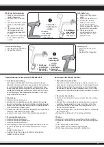
Page 10: ...der Empfangsan lage und entfernen das Ladeger t aus der Steckdose Entnehmen Sie die Akkus dem Sender und dem Modell wenn Sie es f r l ngere Zeit nicht einsetzen Beim Senderakku laden gehen Sie wie fol...

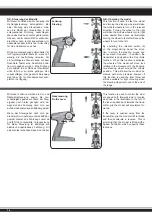
Page 11: ...els can be trimmed and the direction changed Fur thermore the transmitter is equipped with a Dual Rate system and a red LED indicates the state of the battery charge 1 2 3 4 5 6 7 8 9 A B C D E R ckse...

Page 12: ...ar und kennzeichnet die einzelnen Elemente die bedient werden m s sen GB Binding the receiber to the transmitter As with all modern 2 4GHz R C systems the receiver must be bound to the transmitter to...

Page 13: ...an dass der Empf nger betriebsbereit ist c Bringen Sie den Gashebel am Sender in die Neutralposition Ihres Servos oder Speedreglers d Dr cken Sie die Setup Taste am Empf nger Die Signal LED blinkt f...

Page 14: ...s can be reversed if required In addition the transmitter is equipped with a Dual Rate function When this function is activated the wheels of the model will move less relative to the movement of the t...

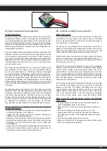
Page 15: ...pf nger ein beim Ausschalten gehen Sie in umgekehrter Reihenfolge vor Setzen Sie nur hochwertige Verbindungskabel und Stecker ein Achten Sie auf gute K hlung des Controllers wickeln Sie ihn keinesfall...

Page 16: ...ss der Schalter in der AUS Position steht Danach schlie en Sie den Antriebsakku an achten Sie dabei unbedingt auf die richtige Polung Stellen Sie den Gassteuerkn ppel und die Trimmung auf die gew nsch...

Page 17: ...aktiviert 4 Wenn die rote und die gr ne LED abwechselnd leuchten ist der Sender nicht eingeschaltet bzw defekt GB LED indicators The LED s give the operator valuable information regarding the ESC whil...

Page 18: ...eitsvorkehrungen Die Firma JAMARA e K schlie t daher ausdr cklich jegliche Haftung f r Sch den aus die durch den fehlerhaften Umgang mit den NiMh Zellen entstehen Bei unsachgem er Verwendung des Akkus...

Page 19: ...nd or powder Safety Policy JAMARA accepts no responsibility for any damage caused by or to its products which is caused by failing to follows these ins tructions The incorrect use of these cells can l...

Page 20: ...gfalt Die Firma JAMARA schlie t daher ausdr cklich jegliche Haftung f r Sch den aus die durch den fehlerhaften Umgang mit den Lithium Polymer Zellen entstehen Bei unsachgem er Verwendung des Akkus bes...

Page 21: ...ls indequate When using the battery incorrect there is a risk of getting fire or acid injuries Overcharging too high power or discharging at low level destroys the cell Protect from mechanical stress...

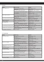
Page 22: ...ng zu niedrig Akku laden bertemperaturabschaltung Speedregler abk hlen lassen Antriebswellen vorn fallen heraus zu gro e Spurbreite Spurbreite verringern GB Troubleshooting Problem Possible cause Solu...

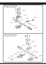
Page 23: ...Differential Front gear assembly diagram Montage hinteres Differential Rear gear assembly diagram 50 5072 50 5076 50 5071 50 5071 50 5071 50 5074 07 9989 50 5073 50 5075 50 5071 50 5074 50 5072 50 50...

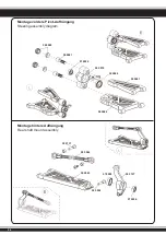
Page 24: ...rdere Pivot Aufh ngung Steering assembly diagram Montage hintere Aufh ngung Rear shaft mount assembly 50 5080 50 5081 50 5131 50 5127 50 5044 50 5043 50 5054 07 9989 07 9996 07 9996 50 5079 50 5046 50...

Page 25: ...25 Montage Sto d mpfer Shock assembly Montage Servo Saver Buffer assembly 50 5133 50 5029...

Page 26: ...26 Montage Radioplatte Upper plate assembly Montage Motorhalterung Motor assembly 03 3215 07 9841 50 5132 50 0151 Motorritzel 3 17 mm 24 Z Motor gear 3 17 mm 24 T 50 5093...

Page 27: ...27 Montage Felgen Reifen Tire assembly 50 5137...

Page 28: ...eering saver set No 50 5036 Spurstange Steering connecting set No 50 5024 Getriebewelle Rear main gear set No 50 5030 Antriebswelle mitte Central shaft set No 50 5026 Motorhalterung Motor mount set No...

Page 29: ...Rims front back No 50 5042 Querlenker unten vorne Front lower suspension set No 50 5065 80 mm Antriebswelle Swing shaft No 50 5138 Sto d mpferhalter vo hi Shock tower set No 50 5043 Querlenker unten...

Page 30: ...windeschraube Connter sunk screw No 50 5052 3 15 Blechschrauben Self tapping cross screw No 50 5055 3 10 Blechschraube Connter sunk screw No 50 5084 Radmitnehmer Hexagonal joint set No 50 5045 7 E cli...

Page 31: ...ohre Antenna pipe set No 50 5156 Kugelkopf Sto d mpfer Aufnahme oben Upper ball head shocks No 50 5140 Dekorbogen Decals No 50 5169 Lightray V2 Dekorbogen Decals No 50 5062 2 10 Stift Pin No 50 5141 K...

Page 32: ...poset ES Tuningteile GB Tuning parts No 07 9880 Futaba Steuerhebel Alu kurz Control arm Alu short No 50 5170 5 x 10 x 4 Kugellager Keramik Bearing Ceramic No 50 3581 Radmuttern selbstsichernd Wheel nu...

Page 33: ...or para usar ruedas 1 8 con 17 mm de montaje hexagonal Rim adapter for using 1 8 wheels with 17 mm hex mount No 13 0155 K hlrippen Cooling fins Achtung 1 8er R der mit 17 mm 6 Kantaufnahme Zur Monta g...

Page 34: ...gnal adjustable by 3rd channel on your transmitter 9 LED Scheinwerfer Spotlight No 50 5284 19 mm LS RS Durchsteckmontage z B f r Rammschutz Rohrrahmen Funktion Dauerlicht 4 LED s Fertig mit Anschlussk...

Page 35: ...h auch die Fahrleistung Deshalb ist es auch wichtig bei Lipo s die Unterspannungs abschaltung Ihres Speedreglers zu aktivieren siehe Anleitung da der Akku sonst Schaden nimmt GB The running time of yo...

Page 36: ...d de Web www jamara ersatzteile de Extra Trade Lindenstra e 82 66787 Wadgassen Tel 06834 9604952 Fax 06834 9604963 E Mail info extra trade de Web www extra trade de Spielwaren und Modellbau B ckle Dr...

Reviews: