3
IT
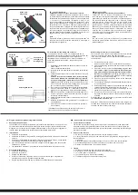
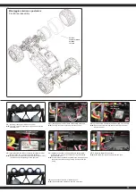
● Mettete la batteria nel vano della batteria, a bordo del veicolo. Fare attenzione che la batteria
sia correttamente fissata con i 2 clip in dotazione e che la batteria non abbia un gioco
eccessivo nel vano appropriato.
● Ora collegare la batteria con il regolatore del modello. Se la spina del regolatore e la spina
della batteria non corrispondono, un cavo adattatore è incluso con il modello.
● Leggere il capitolo sulla trasmittente. Accendere la trasmittente e assicurarsi che i trim siano
in posizione neutrale
● Tenere il modello in aria per il caso che il motore si metta a girare a tutto gas.
● Ora accendere il regolatore di velocità tramite l`interruttore ON / OFF.
● Vi incoraggio ad attivare il ricevitore integrato in unità fail-safe.
Al momento della consegna è spento.
● Se questa è la tua prima auto rc, si consiglia di guidare su una pista piccola per familiarizzare
con il controllo del veicolo e i comandi del trasmettitore.
GB
●
Put the battery into the battery holder in the vehicle. Make sure that the battery holder is scured
properly with the 2 included clips for the battery holder.
●
Now connect the battery to the speed control in the model. If the plug of the speed control and
battery do not match, then you will find a connection lead in your box
●
Turn the radio on and make sure all the trim buttons on the transmitter are in neutral position.
Read the chapter for usage of the transmitter.
●
Keep the car in the air in case that the motor turns at full power.
●
Switch the speed control on the On / Off switch.
● We encourage you now to activate your receiver‘s built-in Failsafe unit.
On delivery it is turned off.
(see chapter Fail Safe).
● If this is your first rc car, we recommend to drive it on a small test track to familiarise yourself
with the control of the vehicle and the controls of the transmitter.
1
Regolatore
ESC
ON/OFF
Batteria
Battery
50 5080
50 5081
07 9996
50 5079
50 5080
50 5081
07 9996
50 5079
IT
Attenzione!
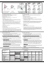
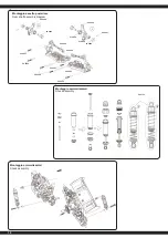
Il veicolo è dotato di una Pivot sospensione anteriore. Questa
ha una serie di vantaggi. E ‚molto robusta e la manutenzione
e´molto facile. Questo è impostato in fabbrica in modo che la
carreggiata non permette agli cardani di saltare fuori. Come con
qualsiasi modello, dopo l´inizio dell’uso si rallentano
di qualche millimetro sia la sospensione sia i bulloni. Questo
gioco minimo, po’ abbastare sotto massimo sforzo per fare
saltare fuori i cardani. Pertanto
è necessario per assicurarsi prima di ogni uso che tutte le viti,
dadi, giochi ecc., sono fissate correttamente. La vita esterna
in plastica 505080 serva per fissare il fuso a snodo sulla vite a
sfera. Questo non deve essere serrata
troppo forte. In caso contrario, lo sterzo non si muove libera-
mente e la guida può essere influenzata negativamente.
GB
Attention!
Your vehicle has a pivot front suspension. This has a number of
advantages. It is very robust and easy to maintain. The set-up of
the car has been done so the drive shaft will not pop out. As with
any model, screws and bolts can losen during break-in of the
car. This can result in tolerance of the drive shaft. The drive shaft
can then pop out if high pressure is applied. The inner ball screw
(item No.: 505081) will enable you to adjust the tolerance resul-
ting in fine adjustments of the track width. For best results when
setting up the pivot ball for the first time, please always adjust
the upper and lower pivot in the same way. Fasten as far as the
pivot can still be pulled up and down easyly but not as far that it
will pop out if you give full steering angle. The outer plastic socket
screw (item No.: 505080) is only used for securing of the steering
knuckle. This should not be too tight, otherwise the steering is
not smooth and the handling can be adversely affected.
IT
Attenzione!
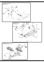
Il giunto omocinetico anteriore e posteriore assorbe la
maggior parte dell’energia del motore e lo passa all’asse
anteriore e posteriore. Per questo, le vite a brugola che tengono
il giunto omocinetico sul asse di uscita prima del primo utilizzo e
in intervalli regolari (5-7 inserti) devono essere controllati e se
necessario avvitare. Nel giunto omocinetico anteriore e pos-
teriore deve essere inserito un anello di gomma. Controllare il
gioco del albero motore. Il margine del gioco dovrebbe essere
di ca. 1-2 mm. Potrebbe essere necessario spostare il giunto
omocinetico per adattare il gioco. Qui deve svitare le vite senza
testa con un cacciavite e regolare il giunto omocinetico.
Dopo di che avvitare le vite senza testa. In caso contrario
l’omocinetico si sposta sul albero di uscita e l’omocinetico e
l’albero centrale possono essere danneggiati.
GB
Attention!
The front and rear bone pan absorbs most of the motor‘s
energy and directs it to the front and rear axles. Therefore,
the hexagon socket screws which hold the bone pans on the
transmission output shafts must be checked and, if necessary,
tightened before the
first use
and in regular intervals e.g 5-7
uses. Insert a rubber ring to the front and the back connection
cup. Please check the tolerance of the drive shaft. The tole-
rance should be approx. 1 – 2mm. You may have to move the
connection cups to adapt the tolerance. Therefore you need to
loosen the grub screws to adapt the connection cup.
Afterwards tighten the grub screws. If not, the connection cups
will move on the gear output shaft. That might cause the con-
nection cup and the middle drive shaft to get damaged.
IT
- Attenzione.
Spegnere sempre il modello subito dopo ogni utilizzo. Subito
dopo ogni utilizzo, la batteria deve essere scollegata dal
modello. La batteria può essere scaricata completamente se
viene lasciata accesa accidentalmente o se viene lasciata
inserita. La scarica profonda causa la perdita di energia della
batteria o può essere danneggiata a tal punto che la carica o
la scarica non è più possibile o la batteria può autoaccendersi
durante la carica o la scarica (pericolo di incendio). Italienisch:
Non tentare mai di caricare o scaricare batterie completamen-
te scariche. La tensione della batteria LiPo non deve mai scendere sotto i 6 volt e quella
della batteria NiMh non deve mai scendere sotto i 4 volt per evitare una scarica profon-
da. La batteria LiPo completamente carica ha una tensione di circa 8,4 volt e la batteria
NiMh di 8,5 volt. Dopo l‘uso, le batterie intatte devono essere ricaricate completamente
subito dopo una fase di raffreddamento di minimo 10 minuti e al più tardi dopo 12 ore
per evitare una successiva scarica profonda per autoscarica. Se le batterie non ven-
gono utilizzate o conservate per un lungo periodo di tempo, è necessario controllarne
la tensione ossia il danneggiamento almeno ogni 3 mesi (con LiPo minimo 8 Volt, con
NiMh minimo 7,4 Volt) se necessario, ricaricarle o smaltirle.
GB
- Danger.
Always switch off the model immediately after each use. Immediately after each use the
battery should be disconnected from the model. The battery can be deeply discharged
by leaving it switched on accidentally or leaving it plugged in. Deep discharge causes
the battery to lose power or can be damaged to such an extent that charging or dischar-
ging is no longer possible or the battery can self-ignite during charging or discharging
(fire hazard). Never attempt to charge or discharge deep-discharge batteries.
The voltage of the LiPo batteries should never be under 6 volt and the NiMh battery
never under 4 Volt to avoid a depth discharge. The fully charged LiPo battery has a
voltage of approx. 8,4 Volt and the NiMH battery 8,5 Volt.
After usage, the intact battery has to be fully charged after a cooling phase of at least
10 min but not longer than 12 hrs. This is to avoid a deep discharge caused by a self-
discharge. When not using or storing the battery´s it has to be checked at least every
three months for voltage (For LiPo min. 8 Volt, for NiMh min. 7,4 Volt.) or damage and if
necessary charged or disposed.


