4
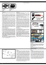
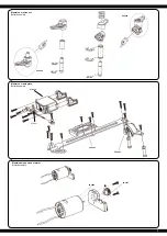
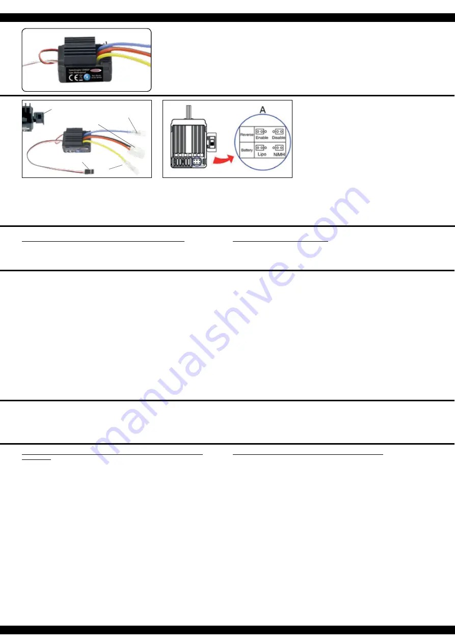
Conexiones del batería
Battery connector
Cable de control
Signal wire
ON/OFF
On/Off switch
Conexiones del motor
Motor connector
Conexiones del motor
Motor connector
ES - Controlador (instalada) Version EP
Datos tecnicos:
Voltaje
7,2 - 7,4 V
Batería
2 Lipo | 6 NiCd/NiMh células
Resistencia inerna Fwd: 0.002 Ohm, Bwd: 0.004 Ohm
BEC-Voltaje
BEC 2A/5V (Linear mode BEC)
Aplicaión
RC-Car 1:10
Protección
Baja tensión de bloque
Carga continua
40 A
Tamaño
~ 45 x 32 x 26 mm
GB - Controller (installed) Version EP
Technical Data:
Operating Voltage
7,2 - 7,4 V
Battery Pack
2 Lipo | 6 NiCd/NiMh Cells
Internal Resistance
Fwd: 0.002 Ohm, Bwd: 0.004 Ohm
BEC Voltage
BEC 2A/5V (Linear mode BEC)
Intended use
RC-Car 1:10
Protection Circuit
Under voltage cut off
Continuous load
40 A
Size
~ 45 x 32 x 26 mm
Si está utilizando una batería Lipo, debe activar el Lipomodo a través del Jumper (puente de
connexión). Antes de llegar a su minima tension,se va a apagar el regulador. Solo asi la bat-
ería lipo está protegido contra descargas o los daños causados por una descarga profunda!
En el umbral de 6 V de tensión total, el regulador se apaga para no descargar la batería. Si
está utilizando una batería NiMh tienes que poner el Jumper en posicion NiMH. El regulador
no se apaga en 6 V de tensión total pero permite una descarga de unos aprox. 4 voltaje total.
This regulator has two battery modes which will be set with jumpers. If you are using a Lipo
battery this jumper has to be set to Lipo. This function protects the lipo battery against deep
discharge and possible damage due to deep discharge! At a threshold voltage of 6 V total
the esc switches autom. off to safe the battery from under voltage. If you are using a NiMH
battery this jumper has to be set to NiMh. The controller allows a voltage less than 6 V down
to 4 V.
¡Atención!
El modelo está protegido contra salpicaduras de agua, pero no es impermeable.
Evitar charcos que pueden tener contacto con el regulador montado en el vehículo. No sumerja
el regulador bajo el agua. Después de cada giro en mojado, el completo regulador se debe estar
completamente seco. Daños y accidente causado por un uso inadecuado o falta de mantenimiento
no está cubierto por la garantía.
WARNING
Your controller is Splash-proof. Not waterproof.
Avoid puddles that are higher than the controller is installed in the vehicle. Do not get the model un-
der water. After each ride in the wet, the complete controller must be thoroughly dried and lubricate
the mechanical components. Damage caused by improper use overload or lack of maintenance is
not covered under warranty.
Uso del Regulador
Para el uso del regulador, siga los siguientes pasos:
• Encienda la emisora y asegúrese de que el recorrido del canal del gas (acelerador) está
programado exactamente para un re corrido del +/- 100%.
• Conecte la batería, con el interruptor del receptor todavía apagado, asegurándose de la
polaridad correcta.
• Encienda el interruptor del receptor.
• Con la batería conectada, el regulador esta “vivo”, así que hay que tener mucho cuidado para
evitar posibles lesiones debido a motores que arrancan repentinamente.
• No conecte la batería con el regulador hasta directamente antes de usar el modelo y vuelva a
desconectarla inmediatamente después del uso del modelo.
• Antes del primer uso en un modelo, realice una comprobación de alcance. Haga esto con el
acelerador a tope, a medio gas y al ralentí y compruebe que no haya ningún tipo de
interferencias. Fíjese también en los servos conectados. Temblores en los servos u
oscilaciones no deseadas también son un indicio de interferencias.
• Si quiere activar el freno mientras el modelo va avanzando, teniendo la palanca del acelerador
hacia delante, tiene que cambiar la palanca de golpe totalmente hacia atrás. Para andar hacia
atrás, tiene que mover la palanca del acelerador a la posición neutral, esperar un momento, y
después mover la palanca hacia atrás hasta el punto deseado.
Using your controller
To operate the ESC, proceed as follows:
• Switch on your transmitter and ensure that the throw for the throttle channel is set to +/-
100%.
• Ensure that the receiver switch is in the OFF position and connect a battery pack ensuring the
correct polarity (+ and -).
• Switch the receiver system ON.
• Once a battery is connected the system is ‘live‘ and extreme caution must be exercised to
prevent injury due to the motor suddenly starting to turn.
• Do not connect the battery pack until directly before operating the model and disconnect the
pack immediate after use.
• Conduct a range test before running the model for the first time. This test should be carried out
at full, half and low throttle and if the servos jitter or make uncontrolled movements do not
operate the model until the reason for the interference has been established and corrected.
• When the vehicle is being driven forwards, pulling the throttle back past the neutral position will
cause the vehicle to brake. To make the vehicle then reverse, the throttle stick must first be
moved back to the neutral position for a short period and then the model will reverse.
• If you want to disable the backward function just set the jumper to disable. If the jumper is set to
enable the backward function is enabled.
Configuración del Regulador
El regulador se calibra automáticamente con la señal de la emisora. Para esto el trim (ajuste fino)
del acelerador de la emisora tiene que estar en posición neutral. Encienda primero la emisora y
después el regulador. El regulador confirma la calibración automática con una melodía corta y
después se encuentra listo para funcionar. Si el regulador no reconoce una señal clara o si el trim
del acelerador no esta en posición neutral, el regulador no se iniciará.
Configuring your controller
The speed controller automatically calibrates itself to the transmitter signal. For this, the trim button
of the gas channel at the transmitter must be set to neutral. Turn on the transmitter and then the
speed controller. The speed controller signals the calibration with a short melody and is ready for
use. In case the speed controller has no clear signal or the trim control is not set to neutral, the speed
controller will not initialize.
Además, para poner en marcha y utilizar el reguladore debe respetar lassiguientes
indicaciones:
• Utilice solamente baterías con un número de elementos que se correspondan con los valores
indicados en datos técnicos.
• Deje enfriar el regulador del todo después de su uso antes de volver a arrancarlo.
• Saque la batería del modelo después de cada uso.
• Es imprescindible encender siempre primero la emisora y despuésel regulador. Al apagarlo
sucede lo mismo en el orden contrario.
• Solamente use conectores y cables de calidad.
• Asegúrese de la buena ventilación del regulador. Bajo ningún concepto debe envolverlo en
gomaespuma o similar. Se prohíbe cualquier modificación de la estructura del modelo ya que
anulará la garantía inmediatamente.
When using the controller please observe the following safety notes:
• Use only batteries which not exceed the max. operating voltage (2 Lipo cells | 6 NiCd/NiMh cells).
• Allow the ESC to cool down completely before operating it again.
• Remove the battery from the model when not in use.
• Always switch off the receiver first and then the transmitter. On switching on, switch on the
transmitter first and then the receiver.
• Only use top quality cables and connectors.
• Make sure that the ESC is adequately cooled and never wrap the unit in anything that insulates.


