8
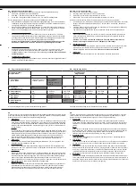
Wichtiger Hinweis:
Zusätzlich zu den Blinksignalen der roten LED werden auch entsprechende akustische Signale
vom Motor erzeugt. Nach jeder Programmierung muss der Regler zuerst ausgeschaltet werden.
Beim Wiedereinschalten wird die neue Konfi guration wirksam.
Important note:
In addition to the red LED blinking, the motor will omit an acoustic signal. After every change to
the values the ESC must be switched off to store the values. The new settings will not be eff ective
until the ESC is re-started.
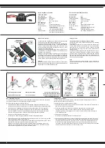
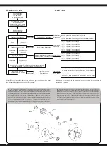
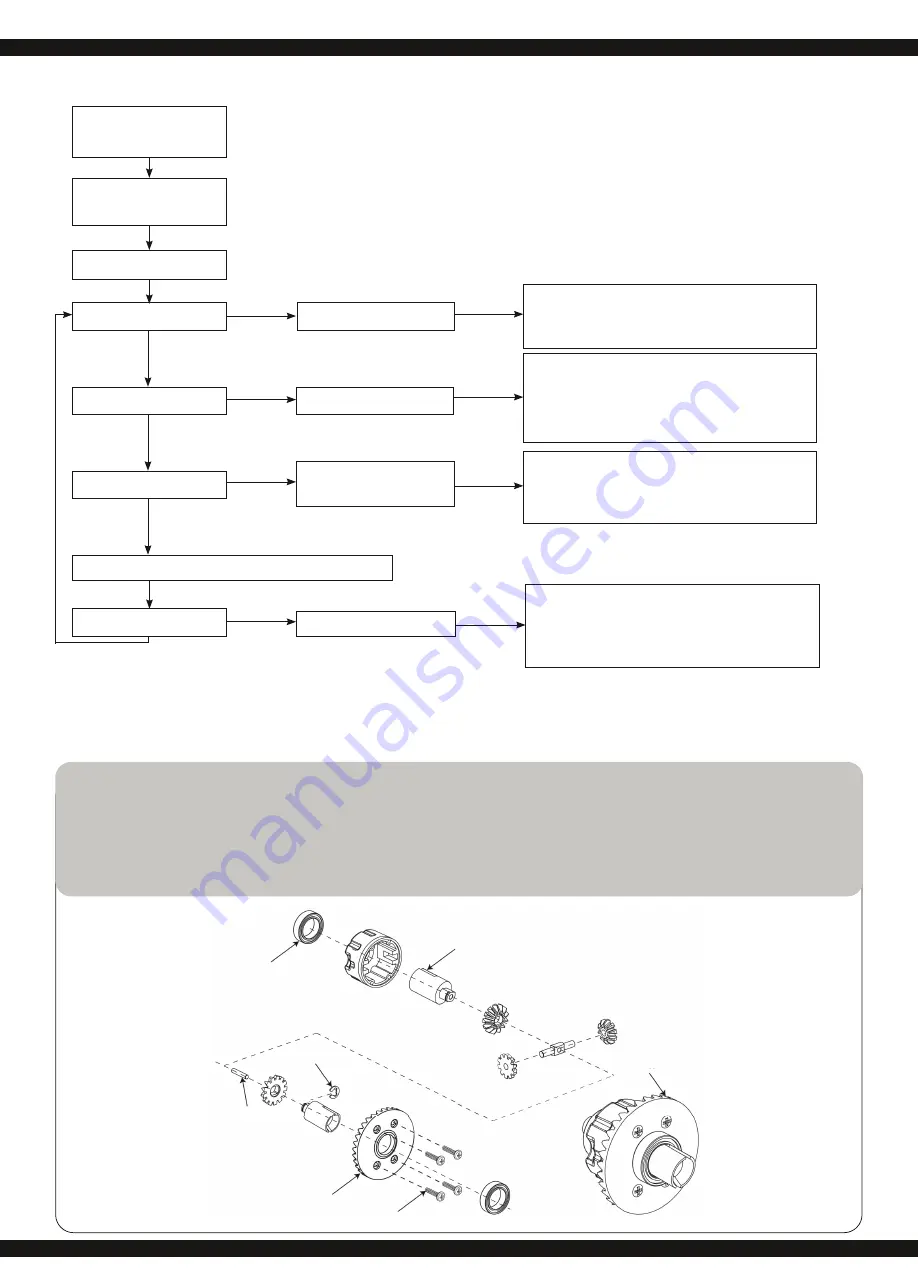
DE - Menüstruktur des Reglers
GB - Menu structure
Regler einschalten, und dabei
’SET’-Taste drücken
Press and hold the ‘SET‘ button
down and switch the receiver on
Die rote LED blinkt
The red LED blinks
Regler ausschalten
Sender einschalten
Turn off the ESC
Switch transmitter ON
Die grüne LED blinkt einmal
The green LED blinks once
Die grüne LED blinkt 2 x
The green LED blinks twice
Die grüne LED blinkt 3 x
The green LED blinks 3 times
Die grüne LED blinkt X x
The green LED blinks X times
Taste 3 Sek.
halten
Press the button
for 3 seconds
Taste 3 Sek.
halten
Press the button
for 3 seconds
Taste 3 Sek.
halten
Press the button
for 3 seconds
Taste lösen
Release button
Taste lösen
Release button
Taste lösen
Release button
Taste lösen
Release button
Taste drücken
Press button
Taste drücken
Press button
Taste drücken
Press button
Taste drücken
Press button
Programmierphase 1, Fahrmodus
Program option 1, Drive mode
Programmierphase 2, Bremsmodus
Program option 2, Brake mode
Programmierphase 3, Unterspannung
Program option 3, Low voltage cut-off
Programmierphase X
Program Option
rote LED blinkt einmal, d.h. Vorwärtsfahrt mit Bremse
Red LED blinks once indicating forwards and brake.
rote LED blinkt zweimal, d.h. Vorwärts- und Rückwärtsfahrt mit Bremse
The red LED blinks twice indicating forwards, reverse and brake.
rote | red LED blinkt | blinks 1 x ► 0 %
rote | red LED blinkt | blinks 2 x ► 5 %
rote | red LED blinkt | blinks 3 x ► 10 %
rote | red LED blinkt | blinks 4 x ► 15 %
rote | red LED blinkt | blinks 5 x ► 20 %
rote | red LED blinkt | blinks 6 x ► 25 %
rote | red LED blinkt | blinks 7 x ► 30 %
rote | red LED blinkt | blinks 8 x ► 40 %
rote | red LED blinkt | blinks 1 x ► aus
rote | red LED blinkt | blinks 2 x ► 2,6 V
rote | red LED blinkt | blinks 3 x ► 2,8 V
rote | red LED blinkt | blinks 4 x ► 3 V
rote | red LED blinkt | blinks 5 x ► 3,2 V
rote | red LED blinkt | blinks 6 x ► 3,4 V
Drücken Sie bitte jeweils die ’SET’-Taste zur Veränderung des jeweili-
gen Wertes, die rote LED zeigt jeweils die Werte an, einmal blinken heißt
Wert 1, zweimal blinken heißt 2, usw.
Press the ‘SET‘ button to select the desired value. The red LED will
indicate which value is selected. 1 X blink indicates value 1, 2 x blinks
indicate value 2 etc.
Alle weiteren Programmierschritte laufen nach dem gleichen Verfahren ab
All of the other menu options are accessed in the same manner.
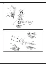
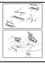
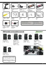
506174
079989
506185
506146
506186
505062
505047
DE
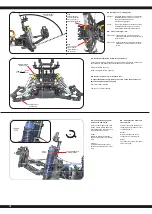
- Bitte überprüfen Sie vor jedem Einsatz sämtliche Schraubverbindungen und Kabelverbindungen auf
korrekten Sitz. Ihr Fahrzeug besitzt eine Pivot Vorderradaufhängung. Diese besitzt eine Vielzahl an Vorteilen.
Sie ist sehr robust und leicht zu warten. Diese ist im Auslieferzustand so eingestellt dass die Spurbreite es nicht
zulässt dass die Antriebswellen herausspringen können. Wie bei jedem Modell werden beim Einfahren natürlich
sowohl Aufhängungsteile als auch Schraubverbindungen im Millimeterbereich gelockert. Dieses entstehende
Spiel kann ausreichen das bei maximaler Belastung eine Antriebswelle herausspringt. Deshalb ist es auch nötig
sich vor jedem Einsatz zu versichern dass alle Schraubverbindungen, Radmuttern, Spiele etc. korrekt sind.
Wenn Sie am Pivotachsschenkel 505079 die innere Kugelschraube 505081 (siehe Ersatzteilliste) verdrehen
stellen Sie damit das Spiel und die sich daraus resultierende Spurbreite ein. Am besten ziehen Sie den Pivot
oben und unten gleichermaßen so weit an, dass die Wellen beim kompletten Lenkeinschlag nicht unter Span-
nung stehen aber auch nicht herausfallen können. Die äußere Kunststoff Inbusschraube 505080 dient nur zum
sichern des Achsschenkels auf der Kugelkopfschraube. Diese sollte auf keinen Fall zu fest angezogen werden.
Da sonst die Lenkung nicht mehr leichtgängig ist und das Fahrverhalten negativ beeinfl usst werden kann.
GB
- Before each use make sure to check all bolt connections and cable connections. Your vehicle has a pivot
front suspension. This has a number of advantages. It is very robust and easy to maintain. The set-up of the car
has been done so the drive shaft will not pop out. As with any model, screws and bolts can losen during break-in
of the car. This can result in tolerance of the drive shaft. The drive shaft can then pop out if high pressure is
applied. The inner ball screw (item No.: 505081) will enable you to adjust the tolerance resulting in fi ne adjust-
ments of the track width. For best results when setting up the pivot ball for the fi rst time, please always adjust
the upper and lower pivot in the same way. Fasten as far as the pivot can still be pulled up and down easyly but
not as far that it will pop out if you give full steering angle. The outer plastic socket screw (item No.: 505080) is
only used for securing of the steering knuckle. This should not be too tight, otherwise the steering is not smooth
and the handling can be adversely aff ected.


