10
GB
- Assembly
Attention:
You do not need glue for this kit.
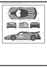
Please attach the stickers at the appropriate place before assembly.
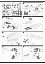
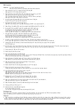
1. Stick sticker 42 on part C21, sticker 46 on part G50 and G49.
Attach parts C21, B15, G49 and G50 to part 73.
2. Stick sticker 44 on part G59, sticker 43 on part G54 and sticker 45 on part G58.
Attach parts G59 and C22 to part C24 and part G54 to part G52.
Then insert the complete part (G52/54) in the hole of C22 as shown in the figure.
Attach part G58 to part C22 as shown in the figure.
3. Insert the previously assembled parts in the position shown in the figure.
Fix part B14 to part 73 and part C16 to part B14.
4. Mount part C26 and C27 on part 73 (see figure).
Attach B7 to the outside of B5. Insert the complete part (B7/B5) on the right into part 73.
5. Attach B8 on the outside of B4. Insert the complete part (B4/B8) into part 73 on the left.
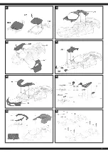
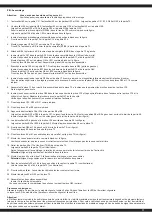
6. Insert part F41 into part E38. Fasten the complete part in G45 (right door).
Insert the bolts of part B10 through the recesses of part B11 and part G45.
Fit part C20 onto parts G45 and B11 as shown in the figure.
Fasten part G46 from bottom to top. Assemble part G56 on the assembled part.
7. Plug part F40 into part E37. Fasten the complete part in G44 (left door).
Insert the bolts of part B13 through the recesses of part B12 and part G44.
Place part C19 on parts G44 and B12 as shown in the figure.
Fasten part G47 from bottom to top. Assemble part G57 on the assembled part.
8. Insert the two lugs of part D28 into part C18 as shown. The lower lugs should be easy to insert.
For the upper lugs light pressure is needed. Then mount part E34 in the holes of part D28 and C18 as shown.
9. Assemble the part C18 that has just been assembled into part 73. Insert the front pins of part C18 only slightly.
Do NOT fix them yet.
10. Insert the upper nose of part G46 into the upper hole of part C18 and the lower pin into the gap between part C18 and the chassis (see figure).
Repeat the procedure with part G47 on the other side. Check that the doors can be opened and closed easily.
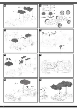
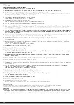
11. Fasten parts C23, D30 and D31 as shown.
12. Fasten parts A1 and B3 as shown.
13. Stick stickers 38 and 39 on parts B9 and B6
Attach parts D29 and D32 to part C17. Attach them to part A2. Mount parts B6 and B9 on the left and on the right side of part A2. Insert parts G51 and
G48 on the left and right sides of part A2 (see figure).
14. Stick stick stickers 24 left and right and 29 in the middle of part A2 (see figure).
Attach parts E33 and E36 to part A2. Mount the assembled part A2 on part 73.
15. Attach parts G55 and 70 to the left and right of part 72 (see figure).
Fasten parts 69 in the corners of part 72.
16. Fasten parts 60 and 61 in the designated places on part 72 (see figure).
17. Mount the front and rear wheels as shown in the figure.
Please make sure that the wheels are fitted correctly. Do not mix up the front and rear wheels.
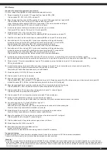
18. Connect parts 60 and 74 and fix them (74/60) in part 72.
Attach part 63 to part 72 (see illustration).
After aligning and assembling, turning one wheel allows the wheel on the other side to be driven to turn.
Caution:
Align the protruding pin and install it in the groove.
19. Mount part 64 on part 72. pay attention to the length of the two cables.
Caution:
Align the pins with the groove when installing the headlights.
20. Attach the stickers 33 and 34 to the correct position at the front on part 72 (see illustration).
Attach parts 65 and 66 to part 72 (see illustration)
21. Attach the loose cables. Connect the cables according to color and shape.
22. Mount parts 62 and G53 on part 72.
23. Assemble the two assembled parts together.
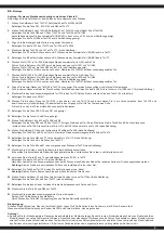
Insert 3 AA batteries in the model
You can close the battery compartment by turning part G53 (lock).
Binding process:
Turn on the model. The light on the model flashes. Insert 2 AA batteries into the transmitter, the LED on the transmitter will flash.
When the LEDs on both the model and the transmitter stop flashing, they are bound.
Attention!
● Never operate your model beyond sight. Both the maximum visibility as well as the max. range of your model will depend on many factors such as
weather, location and interfering frequencies. Therefore, before each use perform a range test with a second person securely holding the model and
also check how the model reacts if there is a signal failure e.g. when empty transmitter batteries are installed.


