8
Nota importante:
Oltre ai segnali lampeggianti del LED rosso, sono generati anche segnali acustici dal motore. Al
termine di ogniprogrammazione, il regolatore deve essere prima spento. Dopo il riavvio, la nuova
configurazione avrà effetto.
Important note:
In addition to the red LED blinking, the motor will omit an acoustic signal. After every change to
the values the ESC must be switched off to store the values. The new settings will not be effective
until the ESC is re-started.
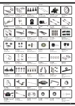
Struttura del menu del regolatore
Menu structure
Accendere il regolatore, mentre si
preme il tasto ‚SET‘.
Press and hold the ‘SET‘ button
down and switch the receiver on
Il LED rosso lampeggia
The red LED blinks
Accendere il regulatore
Accendere il trasmettitore
Turn off the ESC
Switch transmitter ON
Il LED verde lampeggia una volta
The green LED blinks once
Il LED verde lampeggia 2 x
The green LED blinks twice
Il LED verde lampeggia 3 x
The green LED blinks 3 times
Il LED verde lampeggia X x
The green LED blinks X times
Premere il
pulsante
per 3 secondi
Press the button
for 3 seconds
Premere il
pulsante
per 3 secondi
Press the button
for 3 seconds
Premere il
pulsante
per 3 secondi
Press the button
for 3 seconds
Lasciare il tasto
Release button
Lasciare il tasto
Release button
Lasciare il tasto
Release button
Lasciare il tasto
Release button
Premere il
tasto
Press button
Premere il
tasto
Press button
Premere il
tasto
Press button
Premere il
tasto
Press button
Fase di programmazione 1,
modalità di guida
Program option 1, Drive mode
Fase di programmazione 2,
modalità die frenata
Program option 2, Brake mode
Fase di programmazione 3,
sottotensione
Program option 3, Low voltage cut-off
Fase de programmation X
Program Option
Il LED rosso lampeggia una volta, cioè, significa andare avanti con freno.
Red LED blinks once indicating forwards and brake.
Il LED rosso lampeggia due volte indicando marcia avanti, retromarcia e freno.
The red LED blinks twice indicating forwards, reverse and brake.
rosso | red LED lampeggia | blinks 1 x ► 0 %
rosso | red LED lampeggia | blinks 2 x ► 5 %
rosso | red LED lampeggia | blinks 3 x ► 10 %
rosso | red LED lampeggia | blinks 4 x ► 15 %
rosso | red LED lampeggia | blinks 5 x ► 20 %
rosso | red LED lampeggia | blinks 6 x ► 25 %
rosso | red LED lampeggia | blinks 7 x ► 30 %
rosso | red LED lampeggia | blinks 8 x ► 40 %
rosso | red LED lampeggia | blinks 1 x ► aus
rosso | red LED lampeggia | blinks 2 x ► 2,6 V
rosso | red LED lampeggia | blinks 3 x ► 2,8 V
rosso | red LED lampeggia | blinks 4 x ► 3 V
rosso | red LED lampeggia | blinks 5 x ► 3,2 V
rosso | red LED lampeggia | blinks 6 x ► 3,4 V
Si prega di premere il tasto ‚SET‘ per ogni modifica del valore corrente, il LED
rosso indica ciascuno dei valori, lampeggiare una volta significa che è impostato
su valore 1, due volte sul valore 2 ecc.
Press the ‘SET‘ button to select the desired value. The red LED will indicate which
value is selected. 1 X blink indicates value 1, 2 x blinks indicate value 2 etc.
Tutte le fasi seguenti di programmazione si svolgano nella stessa maniera
All of the other menu options are accessed in the same manner.
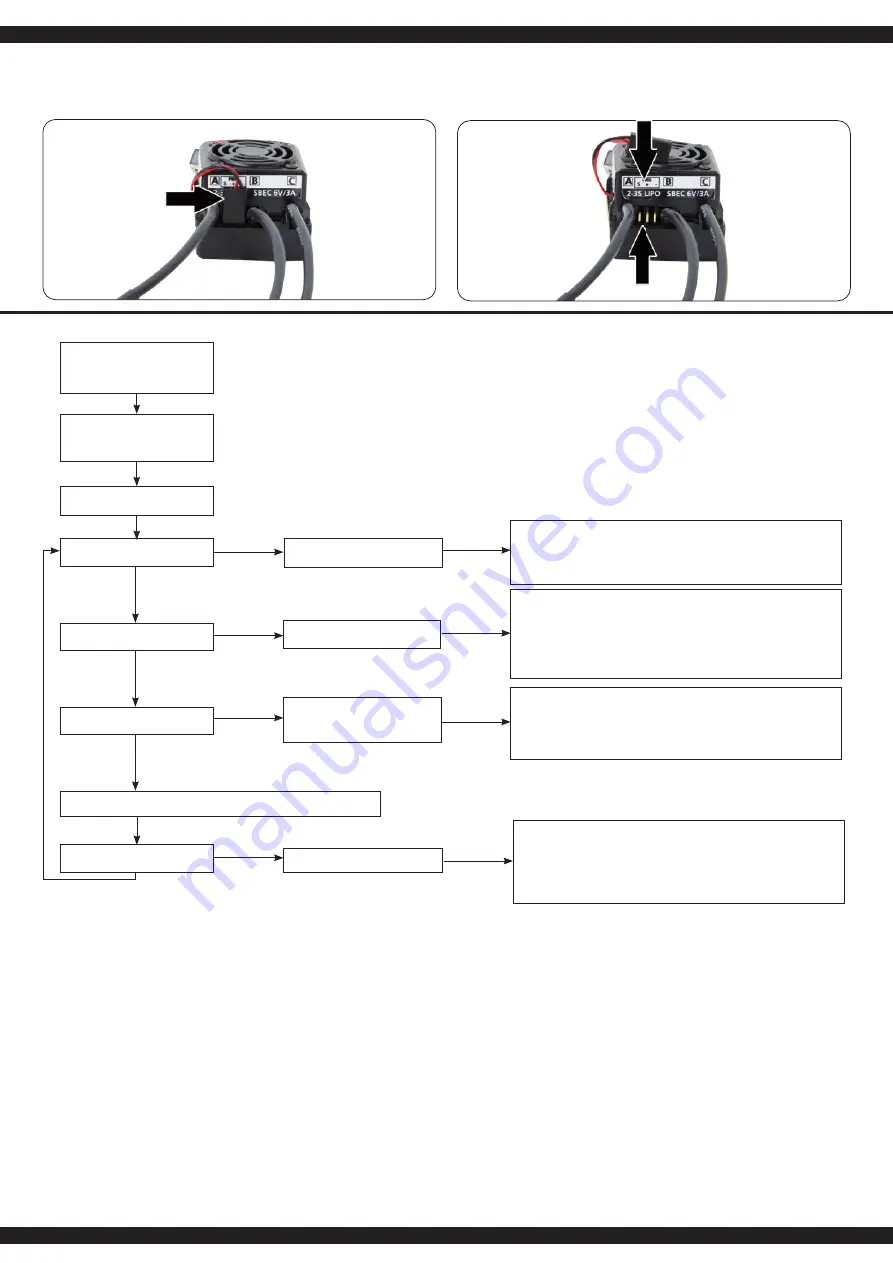
Collegamento di una scheda di programmazione
Per collegare la scheda di programmazione al regolatore di velocità, scollegare il cavo del ventilatore
(1) dal collegamento tra i cavi del motore. Collegare il cavo della scheda di programmazione, accer-
tandosi che il cavo sia collegato correttamente (vedi schema di collegamento Fig. 2). Assicuratevi di
ricollegare il cavo della ventola dopo aver terminato la programmazione.
Connecting the programming card
To connect the programming card to the speed controller, disconnect the fan cable (1) from the
connector between the motor cables. Connect the cable to the programming
card, making sure that the cable is connected correctly (see connection diagram, Fig. 2). Be sure to
reinsert the fan cable after completing the programming.
Cavo per ventilatore
Fan cable
Schema di collegamento
Connect memory card


