background image

Safety Information 

3

General Information 

Technical data 

3

Certifi cate of Conformity 

5

Communications Regulations 

5

Disposal information 

5

Box contents 

5

Features 

5

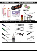
Recommended Accessories 

6

Recommended Tools 

6

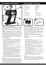
Transmitter 2 Channel 

7

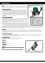
Running in 

9

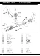
Engine spare parts 

10

General check list before use 

11

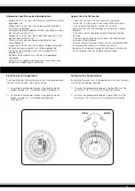
Setting up the 2 speed gear box 

11

Assembly 

12-26

Cutting out the venting holes of the body 

27 

Spare Parts 

28-32

Tuning parts 

33

Notice 

34/35 

3

Content

Safety Information

Models are not toys, and should only be operated by responsible 
clear thinking people. Assembling and maintaining models requires 
a basic level of technical skill, and a sensible logical approach. Any 
error in building, repairing or maintaining the model could result in 
serious injury or damage. 
Technical problems or an incorrectly assembled model may lead to 
the motor unexpectedly beginning to turn. Always stay out of the 
vicinity  of  rotating  parts  and  never  allow  any  item  to  come  into 
contact with a spinning wheel. As neither the manufacturer or the 
dealer  has  any  influence  over  the  way  that  models  are  operated 
they can accept no responsibility for and damage caused. 
If this model is the first radio controlled model which you are att-
empting to build or drive, you should secure the assistance of an 
experienced model pilot.
Never operate the model in a way which may endanger people or 
animals. Before your first drive you should conduct a range check 
of the radio control system, secure the model to a solid object, and 
ensure that you have full control of all functions with the antenna 
collapsed over a distance of at least 25 metres.  
Before  and  after  every  drive  inspect  the  model  for  damage,  and 
rectify any faults before you attempt to take off. The operator is 
responsible for any damage caused by the operation of models. 
Always observe any local laws regarding the operation of model. To 
operate the model, the transmitter must be switched on first, and 
then the model power supply connected. To turn the model off, re-
verse the procedure. It is illegal to operate radio controlled models 
without third party liability insurance. You must ensure that you are 
adequately covered before you drive the model.

Furthermore, the following instructions must be followed: 

-  The  kit  contains  small  parts  which  may  cause  choking  if
  swallowed, keep away from small children. 
-  The  model  should  not  be  changed  in  any  way,  doing  so
  will invalidate the guarantee. 
-  Never come into contact with rotating parts. 
-  Do  not  expose  the  model  or  batteries  to  direct  sunlight,
  always keep them in the shade. 
-  Inspect  the  model  before  and  after  every  drive  for
  damage. 
-  Only ever drive the model if it is in perfect working order. 
-  The  model  can  only  be  driven  in  good  weather.  
  Do not drive in wind, rain or thunder storms. 
-  Find  a  place  to  drive  which  complies  with  any  laws,  and  is
  free from obstacles such as trees or houses. 
-  Remember  that  your  model  is  made  from  such  materials
  as  plastic  and  wood,  and  as  such  is  inflammable.  Keep
  it away from any open flame, or high temperatures. 
-  When  operating  the  model,  switch  on  the  transmitter
  first and then the model, switch off in the reverse order. 
-  Always  ensure  that  the  throttle  stick  is  in  the  low  position
  before you switch on. 

General Information

Technical data

As the company JAMARA e. K. has no influence over the use, main-
tenance or conditions under which our products will operate, we 
accept no responsibility for any damage caused be it of a physical, 
financial or theoretical nature.  JAMARA e. K. will accept no claim 
against it which results directly or indirectly from the operation or  
use of ist products. 
Your Statutory Rights apply, any claim made against us will be based 
solely on the retail price of the product, and limited to the model 
only. This will not apply if we are proved to be legally responsible or 
when gross negligence can be proved.  

Dimensions 

approx. 380 X 200 X 125 mm

Weight 

approx. 1650 g

Scale 

1:10


4 WD

Transmitter 

2 channel

Motor 

SX 2.7 - 2,7 ccm

Attention!

Switch the transmitter on first then the model. When you are fini-
shed first switch off the model then the transmitter.

Summary of Contents for Hoolk RTR

Page 1: ...n manual ready at hand for quick reference even after completing the assembly GB Gebrauchsanleitung Vor dem Gebrauch lesen Sie bitte sorgfältig die Anleitung und bewahren Sie diese bitte auch nach Abschluss der Montage gut auf Instruction Read these instructions carefully before use Please keep these instruction after assembling Hoolk RTR Art Nr Ord No D Vorsichtsmaßnahmen Dieses Modell ist kein S...

Page 2: ...iben Da der Firma JAMARA e K sowohl eine Kontrolle der Handhabung die Einhaltung der Montage und Betriebshinweise so wie der Einsatz des Modells und dessen Wartung nicht möglich ist kann von uns keinerlei Haftung für Verluste Schäden oder Kosten übernommen werden Soweit gesetzlich zugelassen wird die Verpflichtung zur Schadensersatzleistung aus welchen Rechtsgründen auch immer auf den Rechnungswer...

Page 3: ... then the model power supply connected To turn the model off re verse the procedure It is illegal to operate radio controlled models without third party liability insurance You must ensure that you are adequately covered before you drive the model Furthermore the following instructions must be followed The kit contains small parts which may cause choking if swallowed keep away from small children ...

Page 4: ...lektro und Elektronikalt schrottgeräte 2002 96 EG RoHS Beschränkung der Verwendung bestimmter gefährlicher Stoffe in Elektro und Elektronikgeräten 2002 95 EG X X Fernmeldebestimmungen Beachten Sie die Fernmeldebestimmungen in dem Land in dem Sie das Modell einsetzen möchten Bei Fragen wenden Sie sich bitte an unseren Service oder direkt an Ihren Fachhändler Weitere Angaben finden Sie auch im Jamar...

Page 5: ...ctrical and Electronic Equipment WEEE 2002 96 ECC Restriction of Hazardous Substances RoHS 2002 95 ECC X X X Communications Regulations Please observe all rules and regulations referring to the use of ra dio signals radio control which may be in force within the coun try where you are operating your model any queries should be addressed to your dealer Further information can be found on Eu ropean ...

Page 6: ...xagon socket wrench 2 0 mm Inbusschlüssel 2 0 mm Hexagon socket wrench 2 5 mm Inbusschlüssel 2 5 mm Hexagon socket wrench Glühkerzenschlüssel mit Magazin Glow plug key 17 7807 Schraubensicherungslack mittelfest Nut lock medium strength 23 2423 Inbus Revolver Tool 1 5 2 2 5 3 Revolver Tool 1 5 2 2 5 3 19 3210 Kreuzschraubendreher Philips Screwdrivers 19 0074 Spitzzange Needle Nose Pliers Seitenschn...

Page 7: ... der Regel immer auf dem Deckel des Batteriefachs oder der Batteriebox abgebildet Überprüfen Sie vor der Inbetriebnahme immer die Kabel des Empfängers und der Servos auf Beschädigungen und auf korrekten Anschluss Durch ein beschädigtes Kabel oder einen defekten Schalter können Sie die Kon trolle über das Funkfahrzeug verlieren und dadurch Schäden am Fahrzeug oder an anderen Personen oder Gegenstän...

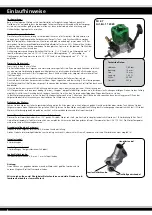
Page 8: ...bei einem transparenten Kraftstoffschlauch auch beobachten Nun wird der Kerzenstecker mit Glühakku angeschlossen und mit dem Seilzug gestartet Die Verteilung des Luft Gasgemisches im Brennraum bedingt das der Strapper einige Male betätigt werden muss bis die ersten Zündungen erfolgen Ziehen Sie den Seilzug möglichst nicht bis zum Anschlag durch sondern versuchen Sie mit kurzen hintereinander folge...

Page 9: ... series of short sharp pulls as this will normally start the motor quickly and reduces the risk of snapping the pull start cord Due to the way in which the fuel air will be distributed within the motor s crank case and cylinder it is quite normal to have to operate the pull cord several times before the motor runs Once the motor is running leave the glow plug bat tery connected for app 1 minute to...

Page 10: ... 9623 Seilzugstarter komplett Ord No Description 12 9601 Cooling head 12 9602 Cooling head screw 12 9603 Cooling head gasket 12 9605 Piston 12 9606 Piston Pin 12 9607 Front ball bearing 12 9608 Connecting rod 12 9609 Rear ball bearing 12 9610 Carb retaining screw 12 9611 Crankcase 12 9612 Crankshaft 12 9613 Rear cover gasket 12 9614 Drive washer 12 9615 Nut 12 9616 Carburetor 12 9620 Drive shaft 1...

Page 11: ...eingeschränkt bewegen lassen Betreiben Sie das Modell nur in sicherer und geeigneter Umgebung Achten Sie auf mögliche Störfrequenzen Diese können den Betrieb Ihres Modells negativ beinflussen Setting Up the 2 Speed Gearbox By adjusting the grub screw in the gearbox you can alter the point at which the second gear engages 1 To make the second gear engage at a higher RPM turn the grub screw 1 8 of a...

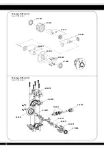
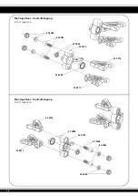
Page 12: ...50 5074 50 5071 50 5085 50 5071 50 5075 50 5073 50 5078 50 5056 50 5071 50 5071 50 5071 50 5074 07 9989 50 5073 07 9989 50 5072 50 5338 Montage Differential Gear Differential Montage Differential Gear Differential ...

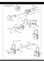
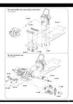
Page 13: ... 50 5301 50 5056 50 5300 50 5348 50 5304 50 5348 50 5304 50 5303 50 5304 50 5352 50 5305 50 5338 50 5338 50 5306 50 5340 50 5307 50 5057 50 5302 50 5339 50 5300 50 5347 Montage Hauptgetriebe Central Gear ...

Page 14: ...50 5080 50 5080 50 5081 50 5081 07 9996 07 9996 50 5079 50 5079 07 9989 07 9989 50 5317 50 5317 50 5316 50 5316 Montage Pivot Frontaufhängung Front Suspension Montage Pivot Frontaufhängung Front Suspension ...

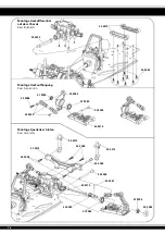
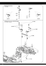
Page 15: ...50 5055 50 5359 50 5090 50 5061 50 5084 07 9996 50 5314 50 5054 50 5028 50 5048 50 5346 50 5055 50 5055 07 9989 Montage Frontdifferential und Getriebe auf dem Chassis Front Bulkhead Montage Querlenker vorne Front assembly ...

Page 16: ...lkhead Montage Heckaufhängung Rear Suspension Montage Querlenker hinten Rear Assembly 50 5319 50 5048 07 9996 50 5320 50 5314 50 5048 50 5313 50 5313 50 5054 50 5048 50 5061 50 5028 50 5090 50 5375 50 5084 07 9996 07 9989 07 9989 50 5082 50 5055 50 5054 50 5318 ...

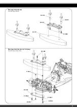
Page 17: ...17 50 5311 50 5312 50 5313 50 5313 50 5048 50 5312 50 5048 50 5055 50 5055 50 5036 50 5048 17 7443 50 5048 Montage Frontrammer Front Bumper Plate Montage Frontrammer am Fahrzeug Front Bumper Assembly ...

Page 18: ...18 50 5310 50 5310 50 5309 50 5309 17 7143 50 5048 50 5048 Montage Servo Saver Servo Saver Montage Servo Saver und Lenkstangen Servo Saver Assembly ...

Page 19: ...19 50 5324 50 5324 Montage Stoßdämpfer Shocks Montage Stoßdämpferfedern Shock Springs ...

Page 20: ...20 50 5049 50 5052 50 5322 50 5324 50 5324 50 5324 50 5057 50 5057 50 5057 50 5057 50 5324 Montage Stoßdämpfer vorne Front Shocks Montage Stoßdämpfer hinten Rear Shocks ...

Page 21: ...21 50 5334 50 5333 50 5045 50 5332 11 2020 50 5351 17 7101 17 7101 50 5351 07 0806 50 5331 07 0806 50 5355 03 1124 Montage Motor und Kupplung Engine Montage Resorohr Muffler ...

Page 22: ...22 50 5352 50 5331 50 5330 Montage Krümmer und Resorohr Muffler Assembly Montage Motor auf dem Chassis Engine assembly ...

Page 23: ...23 50 5321 50 5057 50 5321 50 5328 50 5055 50 5048 Montage RC Anlage Gas Bremsservo Upper Montage Radioplatte Kraftstofftank Upper Plate ...

Page 24: ...24 50 5308 50 5048 50 5048 50 5048 Montage Lenkservo Steering Servo ...

Page 25: ... der Bremse Position where brake starts working Verstellen Sie Stellring A B wie abge bildet Set up A and B screws as shown Vergaser muss vollständig geöffnet sein Check if carburator open fully Bremse muss ziehen Check if brake works properly Montage Gas Bremsgestänge Throttle Assembly Gaseinstellung Throttle Adjustment Leerlauf Neutral Vollgas High Bremse Brake ...

Page 26: ...26 50 5373 50 5373 17 7444 17 7444 Montage der Räder Wheel Assembly ...

Page 27: ... Zu und Abluft zu gewährleisten Ohne diese Öffnungen kann sich der Mo tor zu stark erhitzen und Schaden nehmen Des Weiteren kann eine erweiterte Luftzufuhr die Leistung Ihres Motors erhöhen Cutting out the venting holes of the body For better cooling and air inlet for the motor it is neccessary to cut out venting hole You can apply these cut outs by using the Jamara Knife Edge Reamer Item No 28178...

Page 28: ...2 Lager Getriebewelle Haxagonal joint set Art Nr Ord No 50 5305 Bremsexcenter Bremshebel Brake cam set Art Nr Ord No 50 5308 Lenkstange Servo pulling rod Art Nr Ord No 50 5072 Kegelzahnrad mit Welle Main gear Art Nr Ord No 50 5338 Knochenpfannen Joint cup Art Nr Ord No 50 5303 Kupplung zweiter Gang Two speed clutch Art Nr Ord No 50 5306 Bremsscheibe Brake disk Art Nr Ord No 50 5309 Spurstangen Ste...

Page 29: ...ten Rear shaft hub Art Nr Ord No 50 5322 Servo Saver Verbindungs platte Upper suspension plate Art Nr Ord No 50 5335 Antriebswelle mitte Central shaft Art Nr Ord No 50 5312 Rammschutzhalter Bumper Set Art Nr Ord No 50 5079 Achsschenkel vorne Steering hub set Art Nr Ord No 50 5316 Querlenker oben Upper suspension arm set Art Nr Ord No 50 5319 Querlenkerhalter hinten Rear lower clip slice Art Nr Ord...

Page 30: ...raftstofftank Fuel tank set Art Nr Ord No 50 5331 Kupplungsglocke 17 22 Z Clutch gear 17 22 T Art Nr Ord No 50 5334 Kupplungsbacken Clutch Art Nr Ord No 50 5359 Chassis Chassis Art Nr Ord No 50 5054 Querlenkerstifte oben außen Suspension arm shaft set Art Nr Ord No 50 5357 Karosserie Body Art Nr Ord No 11 2020 Motor SX 2 7 Engine SX 2 7 Art Nr Ord No 50 5337 Getriebe 2 Gang komplett Central gear 2...

Page 31: ...agonal screw Art Nr Ord No 50 5352 3 x 28 mm Blechschraube Self tapping cross screw Art Nr Ord No 50 5046 E clip Ø 4 mm Art Nr Ord No 50 5347 10 x 19 x 5 mm Kugellager Ball bearing Art Nr Ord No 07 0806 5 x 10 x 4 mm Kugellager Ball bearing Art Nr Ord No 50 5048 3 x 10 mm Blechschraube Self tapping cross screw Art Nr Ord No 17 7143 M3 x 8 mm Gewindeschraube Counter sunk tapped cross screw Art Nr O...

Page 32: ...enschraube Set screw Art Nr Ord No 50 5354 5 x 8 x 0 3 mm Distanzring Shim Art Nr Ord No 17 7443 M3 Stoppmuttern Nylon Nut Art Nr Ord No 50 5346 Antriebswellen vorne Front driver shaft Art Nr Ord No 50 5057 M3 x 12 mm Gewindeschraube Cross screw Art Nr Ord No 03 1132 M4 x 4 Madenschraube Set screw Art Nr Ord No 50 5355 3 x 6 x 0 3 mm Distanzring Shim Art Nr Ord No 17 7444 M4 Stoppmuttern Nylon Nut...

Page 33: ...ck tower set alu Art Nr Ord No 50 5374 Original Übersetzung Kupplungsglocke Alu 2 Gang 17 22 Z Original Transmission Clutch gear alu 2 speed 17 22 T Art Nr Ord No 50 5361 Querlenker Alu vorne unten Front lower suspension arm alu Art Nr Ord No 50 5369 Stoßdämpfer Alu vo hi Shock set alu Art Nr Ord No 50 5362 Querlenker Alu vorne oben Front upper suspension arm alu Erhältliche Tuningteile Tuning Par...

Page 34: ...34 Notizen Notice ...

Page 35: ...35 Notizen Notice ...

Page 36: ...________________ E mail _______________________________ Bitte senden Sie den Katalog für mich an folgenden Fachhändler Please send the catalogue to the following specialist dealer Ihr Fachhändler Your dealer __________________________________________________ __________________________________________________ __________________________________________________ _______________________________________...

Reviews: