background image

8

GB - Getting Started

Make sure that all parts from the box content are included. Trans-

mitter, Car, Charger, battery pack.

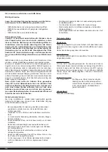
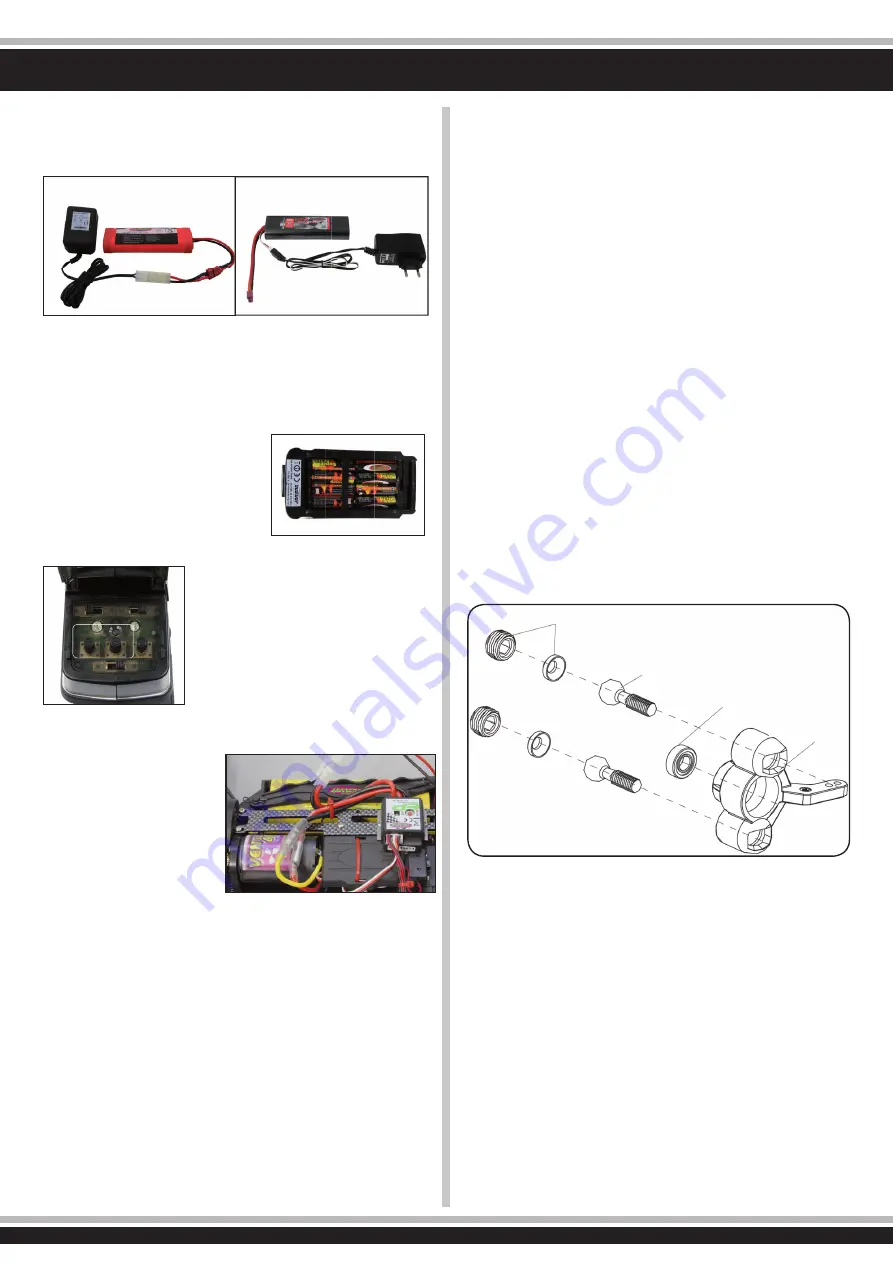
The battery pack has to be charged before use. Plug the charger 

into a 230V outlet. Connect the charger to the battery. If the plug 

of the charger and battery do not match, then you will fi nd a con-

nection lead in your box. The average charging time of the empty 

battery is about 6-8 hours.

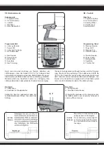
Place  8  pieces  of  AA  batteries  into 

the transmitter. If rechargebale, ple-

ase also make sure these are fully 

charged.

Read the chapter for usage of the 

transmitter and its controls carefully. 

Turn the radio off and make sure all the 

trim buttons on the transmitter are in 

neutral position.

You  have  purchased  a  RTR  model, 

which means it should be ready for 

immediate use after charging all batte-

ries. You need to check the car, electro-

nics and all plastic parts after each use 

to  make  sure  no  parts  are  damaged. 

Also all the moving parts must be checked for their clearance, 

bolts and screws that they 

are tight.

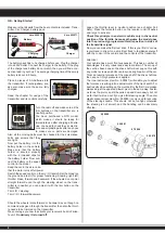
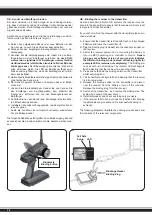
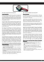
Now  put  the  battery  into  the 

battery holder in the vehicle. 

Make sure that the battery 

holder is secured properly 

with the 2 included clips for 

the battery holder. Now con-

nect the battery to the speed 

control in the model.

Keep the car in the air in case 

that the motor turns at full power.

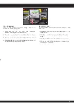
Switch the speed control on the On / Off switch. Set the model on 

the ground and test it for proper functioning. Steering right/ left, 

throttle/ brake, forward and backward. If the wheels do not point 

straight forward even though the steering wheel on the trans-

mitter is in neutral, you can adjust it with the trim button on the 

transmitter.

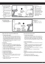
Trim L/R = steering

Trim V/R = forward/backward

Should the wheels rotate forward or backward, even though no 

command was given through the transmitter, then also the thrott-

le needs to be trimmed on the transmitter.

We encourage you now to activate your receiver‘s built-in Failsa-

fe unit. 

On delivery it is turned off. 

Leave  the  throttle  lever  in  neutral  position  (see  chapter  Fail 

Safe). Press the fail-safe button on the receiver until it fl ashes 

and let go to activate. 

Check this principle in an electric vehicle only in the neutral 

position of the throttle, because otherwise the model goes 

into the previously programmed throttle position in a loss of 

the transmitter signal.

Now you can make the fi rst test drive. If this is your fi rst rc car, we 

recommend to drive it on a small test track to familiarise yourself 

with the control of the vehicle and the controls of the transmitter. 

Attention! 

Your vehicle has a pivot front suspension. This has a number of 

advantages. It is very robust and easy to maintain. The set-up of 

the car has been done so the drive shaft will not pop out. As with 

any model, screws and bolts can losen during break-in of the car. 

This can result in tolerance of the drive shaft. The drive shaft can 

then pop out if high pressure is applied. 

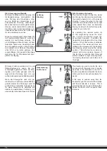
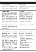
The inner ball screw (item No.: 505081) will enable you to adjust 

the tolerance resulting in fi ne adjustments of the track width. For 

best results when setting up the pivot ball for the fi rst time, please 

always adjust the upper and lower pivot in the same way. Fasten 

as far as the pivot can still be pulled up and down easyly but not 

as far that it will pop out if you give full steering angle. The outer 

plastic socket screw (item No.: 505080) is only used for securing 

of the steering knuckle. This should not be too tight, otherwise 

the steering is not smooth and the handling can be adversely 

affected.

On/Off

L/R  F/B

Trim

50 5080

50 5081

07 9996

50 5079

Charger

Battery

Charging 

adapter

Charger

Battery

Vers. 053270

Vers. 053271

ESC

On/Off

Battery

ESC/Battery
Connector

Summary of Contents for Lightray V2 RTR 2,4 GHz

Page 1: ...DE Gebrauchsanleitung GB Instruction DE GB Lightray V2 RTR 2 4 GHz Art Nr Ord No 05 3255 NiMh 05 3256 LiPo Frei verwendbar in Permittend in EU CH ...

Page 2: ...meine Sicherheitshinweise Montieren Sie den Kit nur an Plätzen außerhalb der Reichweite von Kinder Im Montagesatz sind kleine Teile vorhanden die evtl verschluckt werden können sie dürfen nicht in die Hände von Kleinkindern gelangen Vermeiden Sie das Fahren des Modells an überfüllten Plätzen und in der Nähe von kleinen Kindern Fahren Sie nie auf öffentlichen Straßen Betreiben Sie dieses Modell nie...

Page 3: ... sunlight always keep them in the shade General Safety Instructions Assemble this kit only in places out of children s reach The kit contains small parts which may cause choking if swallowed keep away from small children NEVER fly your model over people and never operate the model in way which may endanger people small children or animals Never operate the model on rain or over damp surfaces this ...

Page 4: ...hende Entsorgung der Elektro bauteile Fernsteuerung Ladegerät und Modell usw Bitte werfen Sie diese nur in die dafür vorgesehenen Sammelboxen bei den Kommunen Lieferumfang 4WD Modell Fernsteuerung 2 4 GHz Fahrakku Ladegerät 230 V Ladegerät 230 V mit integriertem Balancer 053256 Elektro Motor fertig montiert Elektro Regler fertig montiert 1 Servo fertig montiert Lackierte Karosserie Dekorbogen Anle...

Page 5: ...for the proper use and handling including without limitation the assembly the charging process the use and choice of the ope ration area Please refer to the operating and user instructions it contains important information and warnings Attention Switch the transmitter on first then the model When you are finisished first switch off the model then the transmitter Certificate of Conformity JAMARA e ...

Page 6: ...ight lange No 23 2060 Doppelseitiges Klebeband Doublesided power tape No 23 0409 20 g Wheel blood Reifenkleber Rim Glue No 28 1904 Stoßdämpferöl Louise Shock Oil Louise No 23 2423 Schraubensicherungslack mittelfest Nut lock medium strength No 23 0461 400 ml Spezial Reinigungsschaum Special cleaning foam No 15 3065 X Peak 90 Touch Ladegerät Charger No 50 5401 klein small Karosseriesplint Body clips...

Page 7: ...chen Sie den Speedregler durch das aus trimmen des Gastrimmreglers am Sender in die Neutralstellung zu trimmen Wir empfehlen Ihnen nun die in Ihren Empfänger integrierte Failsafe Einheit zu aktivieren Im Auslieferzustand ist diese deaktiviert In dem Sie während Sie den Gashebel am Sender in Neutralstellung lassen siehe Kapitel Fail Safe und auf die Fail Safetaste am Empfänger drücken bis diese bli...

Page 8: ...ven though no command was given through the transmitter then also the thrott le needs to be trimmed on the transmitter We encourage you now to activate your receiver s built in Failsa fe unit On delivery it is turned off Leave the throttle lever in neutral position see chapter Fail Safe Press the fail safe button on the receiver until it flashes and let go to activate Check this principle in an el...

Page 9: ...z Band grundsätzlich störunempfindlicher Andererseits ist aber das Binden eines Empfängers an den zugehörigen Sender unbedingt notwendig Der 2 Kanal Sender ist für die Lenkung und die Fahrfunktion mit hochwertigen Gebern ausgestattet Zum Betrieb müssen 8 Mig non Batterien oder Akkus der gleichen Größe eingesetzt werden Achten Sie absolut genau darauf dass die Batterien bzw Akkus immer genügend Kap...

Page 10: ... der Empfangsan lage und entfernen das Ladegerät aus der Steckdose Entnehmen Sie die Akkus dem Sender und dem Modell wenn Sie es für längere Zeit nicht einsetzen Beim Senderakku laden gehen Sie wie folgt vor 1 Legen Sie die Akkuzellen polrichtig ein 2 Stecken Sie das Ladegerät in eine Steckdose 3 Stecken Sie das Ladekabel in die Ladebuchse des Senders 4 Entfernen Sie das Ladegerät aus der Steckdos...

Page 11: ...els can be trimmed and the direction changed Fur thermore the transmitter is equipped with a Dual Rate system and a red LED indicates the state of the battery charge 1 2 3 4 5 6 7 8 9 A B C D E Rückseite F Ladebuchse G Anschluss für Simulatorkabel Sollten Sie über die Ladebuchse laden bit te Batteriefachdeckel öffnen Dies dient der Kühlung G F Befestigen Sie die 2 4 GHz An tenne senkrecht wie auf ...

Page 12: ...g dar und kennzeichnet die einzelnen Elemente die bedient werden müs sen GB Binding the receiber to the transmitter As with all modern 2 4GHz R C systems the receiver must be bound to the transmitter to ensure that the receiver will only react to signals from that transmitter If you wish to re bind the receiver with the transmitter please pro ceed as follows A Ensure that the transmitter is fitted...

Page 13: ...t an dass der Empfänger betriebsbereit ist c Bringen Sie den Gashebel am Sender in die Neutralposition Ihres Servos oder Speedreglers d Drücken Sie die Setup Taste am Empfänger Die Signal LED blinkt für 3 Sekunden siehe Abb links e Lassen Sie sie wieder los Die Einstellung ist gespeichert 3 Testen der Einstellungen a Schalten Sie den Sender ein b Schalten Sie den Empfänger ein c Schalten Sie den S...

Page 14: ...es can be reversed if required In addition the transmitter is equipped with a Dual Rate function When this function is activated the wheels of the model will move less relative to the movement of the transmit ters steering wheel around the middle position This will allow the model to be steered with more precision however if this function is used the total throw will still be available for tight c...

Page 15: ...Empfänger ein beim Ausschalten gehen Sie in umgekehrter Reihenfolge vor Setzen Sie nur hochwertige Verbindungskabel und Stecker ein Achten Sie auf gute Kühlung des Controllers wickeln Sie ihn keinesfalls in Schaumgummi oder ähnlichem ein GB Controller installed Version Splinter EP Safety Instructions It is possible that an electric engine may begin to rotate when connected to a power source this m...

Page 16: ...ass der Schalter in der AUS Position steht Danach schließen Sie den Antriebsakku an achten Sie dabei unbedingt auf die richtige Polung Stellen Sie den Gassteuerknüppel und die Trimmung auf die gewünschte Neutralposition Die Vorbereitungen für die Konfiguration sind damit abgeschlossen Danach gehen Sie wie folgt vor 1 Schalten Sie den Sender ein 2 Danach schalten Sie über den Schalter des Reglers d...

Page 17: ... aktiviert 4 Wenn die rote und die grüne LED abwechselnd leuchten ist der Sender nicht eingeschaltet bzw defekt GB LED indicators The LED s give the operator valuable information regarding the ESC whilst in use 1 When the red and green LED s are illuminated the ESC is in the neutral position 2 When the green LED is illuminated the ESC is in forwards mode 3 When the red LED is illuminated the ESC i...

Page 18: ...eitsvorkehrungen Die Firma JAMARA e K schließt daher ausdrücklich jegliche Haftung für Schäden aus die durch den fehlerhaften Umgang mit den NiMh Zellen entstehen Bei unsachgemäßer Verwendung des Akkus kann dieser explodieren und oder brennen Es besteht Brand oder Verätzungsgefahr Überladen zu hohe Ströme oder Tiefentladen zerstört die Zelle Vor mechanischer Belastung Quetschen Drücken Biegen Bohr...

Page 19: ...and or powder Safety Policy JAMARA accepts no responsibility for any damage caused by or to its products which is caused by failing to follows these ins tructions The incorrect use of these cells can lead to an explosion and or ire Risk of injury Over charging the use of too high currents or deep dischar ging may damage the cells Protect from mechanical damage crushing dents bending or piercing Ne...

Page 20: ...rgfalt Die Firma JAMARA schließt daher ausdrücklich jegliche Haftung für Schäden aus die durch den fehlerhaften Umgang mit den Lithium Polymer Zellen entstehen Bei unsachgemäßer Verwendung des Akkus besteht Brand oder Verätzungsgefahr Überladen zu hohe Ströme oder Tiefentladen zerstört die Zelle Vor mechanischer Belastung Quetschen Drücken Biegen Bohren schützen Akkus keinesfalls öffnen oder aufsc...

Page 21: ...lls indequate When using the battery incorrect there is a risk of getting fire or acid injuries Overcharging too high power or discharging at low level destroys the cell Protect from mechanical stress squeezing pushing bending drilling Never open or cut open do not throw into fire keep away from children Handle damaged or leaking battery with care Injuries or damages to the product can occure Unde...

Page 22: ...ng zu niedrig Akku laden Übertemperaturabschaltung Speedregler abkühlen lassen Antriebswellen vorn fallen heraus zu große Spurbreite Spurbreite verringern GB Troubleshooting Problem Possible cause Solution Model does not respond Battery or batteries empty or defective Charge battery or replace Motor broken Replace motor Loose or damaged cable Reconnect cable or replace Transmitter turned off lost ...

Page 23: ...s Differential Front gear assembly diagram Montage hinteres Differential Rear gear assembly diagram 50 5072 50 5076 50 5071 50 5071 50 5071 50 5074 07 9989 50 5073 50 5075 50 5071 50 5074 50 5072 50 5023 50 5022 50 5024 50 5073 07 9989 50 5076 ...

Page 24: ...ordere Pivot Aufhängung Steering assembly diagram Montage hintere Aufhängung Rear shaft mount assembly 50 5080 50 5081 50 5131 50 5127 50 5044 50 5043 50 5054 07 9989 07 9996 07 9996 50 5079 50 5046 50 5041 50 5042 ...

Page 25: ...25 Montage Stoßdämpfer Shock assembly Montage Servo Saver Buffer assembly 50 5133 50 5029 ...

Page 26: ...26 Montage Radioplatte Upper plate assembly Montage Motorhalterung Motor assembly 03 3215 07 9841 50 5132 50 0151 Motorritzel Ø 3 17 mm 24 Z Motor gear Ø 3 17 mm 24 T 50 5093 ...

Page 27: ...27 Montage Felgen Reifen Tire assembly 50 5137 ...

Page 28: ...teering saver set No 50 5036 Spurstange Steering connecting set No 50 5024 Getriebewelle Rear main gear set No 50 5030 Antriebswelle mitte Central shaft set No 50 5026 Motorhalterung Motor mount set No 08 1468 Speedregler EP Brushless ESC set No 50 5031 Chassis Chassis No 14 0058 NiMH SunPower 2000 6N 7 2V Akku Battery No 13 0590 Venti 600 E Motor Electric motor No 50 5037 Rammer Set Bumper plate ...

Page 29: ...s Rims front back No 50 5042 Querlenker unten vorne Front lower suspension set No 50 5065 80 mm Antriebswelle Swing shaft No 50 5138 Stoßdämpferhalter vo hi Shock tower set No 50 5043 Querlenker unten hinten Rear lower suspension set No 50 5134 Heckspoiler Wing No 50 5085 Kegelzahnrad A diff Differential bevel gear set No 50 5072 Kegelzahnrad m Welle Main gear No 50 5073 Tellerzahnrad Bevel gear N...

Page 30: ...ndeschraube Connter sunk screw No 50 5052 3 15 Blechschrauben Self tapping cross screw No 50 5055 3 10 Blechschraube Connter sunk screw No 50 5084 Radmitnehmer Hexagonal joint set No 50 5045 Ø 7 E clip No 50 5047 Ø 2 5 E clip No 50 5080 Pivot Schrauben Ball head nut set No 50 5081 Pivot Kugelkopfschrauben Ball head screw set No 50 5127 Achsschenkel hinten Rear shaft hub set No 50 5054 Querl Stifte...

Page 31: ...rohre Antenna pipe set No 50 5156 Kugelkopf Stoßdämpfer Aufnahme oben Upper ball head shocks No 50 5140 Dekorbogen Decals No 50 5169 Lightray V2 Dekorbogen Decals No 50 5062 2 10 Stift Pin No 50 5141 Karosserie Body No 50 5168 Lightray V2 Karosserie Body No 50 5180 Karosserie klar Body clear No 50 5159 Reifen Body clear No 50 5157 Felgen Rims No 50 5160 Felgenringe Rim ring DE Ersatzteile GB Spare...

Page 32: ...iposet ES Tuningteile GB Tuning parts No 07 9880 Futaba Steuerhebel Alu kurz Control arm Alu short No 50 5170 5 x 10 x 4 Kugellager Keramik Bearing Ceramic No 50 3581 Radmuttern selbstsichernd Wheel nuts self locking No 09 0092 Hochstrom Stecker Buchse High current connector No 08 1456 Brushless Set Car Brushless Car set No 36 0110 1 10 Car Liposet Liposet No 50 5285 Empfängerbox Receiver Box No 1...

Page 33: ...dor para usar ruedas 1 8 con 17 mm de montaje hexagonal Rim adapter for using 1 8 wheels with 17 mm hex mount No 13 0155 Kühlrippen Cooling fins Achtung 1 8er Räder mit 17 mm 6 Kantaufnahme Zur Monta ge am Lightray ist Radadap ter 503554 erforderlich Please note 1 8s cale wheels with 17mm hex mount You need Adapter 503554 to mount this wheels on Lightray ...

Page 34: ...rung Signal adjustable by 3rd channel on your transmitter 9 LED Scheinwerfer Spotlight No 50 5284 Ø 19 mm LS RS Durchsteckmontage z B für Rammschutz Rohrrahmen Funktion Dauerlicht 4 LED s Fertig mit Anschlusskabel Left Right pin through mounting e g for impact protection tube frame Function Continuous light 4 LEDs Done with connection cable LED Badge No 70 2500 Highlights 576 Extra helle einzel an...

Page 35: ...ich auch die Fahrleistung Deshalb ist es auch wichtig bei Lipo s die Unterspannungs abschaltung Ihres Speedreglers zu aktivieren siehe Anleitung da der Akku sonst Schaden nimmt GB The running time of your model see diagram above depends on the ca pacity of your battery in mAh The average running time with a 2000 mAh battery is about 10 minutes With the 4500 mAh battery for approximately 30 minutes...

Page 36: ...nd de Web www jamara ersatzteile de Extra Trade Lindenstraße 82 66787 Wadgassen Tel 06834 9604952 Fax 06834 9604963 E Mail info extra trade de Web www extra trade de Spielwaren und Modellbau Böckle Dr A Heinzlestr 3 AT 6840 Götzis Tel 0043 0 5523 52220 Fax 0043 0 5523 522204 E Mail modellbau boeckle aon at Web www modellbau boeckle com Modellflugshop Am Bahndamm 6 86650 Wemding Tel 07151 5002192 F...

Reviews: