5
Using Your ESC for the First Time
The ECS can be programmed by taking the following steps:
1. Switch on the transmitter and move the throttle stick to the
full throttle position.
2. Connect the flight pack (battery).
3. Wait until you hear two short tones (_ _ * *). this indicates
that the ESC in programming mode.
4. If the throttle stick is moved to the low position within 5
seconds you will hear another tone which will indicate that
the throttle stick has been re-calibrated. If the throttle stick
is not moved, a series of tones will be emitted after a short
period of time. These bleeps indicate the functions which
can be programmed, please refer to the section
‘Programming Options’.
5. Once the option which you wish to change has been reached
move the throttle stick immediately back to the low or off
position. That function will then be changed to the option
which you have chosen. The ESC will confirm you actions
by emitting two bleeps (* *).
6. When programming an Xetronik ESC only one function may
be altered each time that you access the Programming
Mode. If several functions are to be changed the flight pack
must be disconnected for at least 5 seconds after making an
alteration before you access the Programming Mode agin to
make the next change.
The easiest way to program a Xetronik ESC is to purchase a Pro-
gramming Card which is available from your dealer.
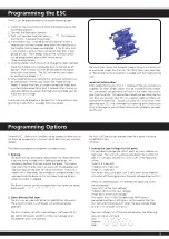
The illustration shows the Xetronik Programming Card which can
be purchased under the Part No. 08 1905 from your local dea-
ler. Please refer to the instructions included with the Programming
Card.
Important Information:
When programming your ESC it is important that you remove any
propellers or rotor blades which may be attached to the engine.
This is to prevent the possibility of injury in the event that the en-
gine starts to rotate. This precaution should also be taken the first
time that you connect your ESC to a power supply or when cali-
brating the throttle stick. Please put safety first at all times when
operating your ESC and remember that rotating parts could cause
injury or damage to you or those around you whenever you ope-
rate the unit.
Programming the ESC
Xetronik ESC’s allow many functions to be altered to allow you to
set them up to operate in a manner which best suits you and your
models.
The following programming options are open to you:
1. Braking:
The brake can be activated or deactivated. We recommend that
if you are flying a model with a folding propeller on, for
example a Hotliner, that you activate the brake. This means
that when the throttle stick is at low or off, the propeller will
stop turning and fold back to reduce resistance. If you fly a
model with a fixed prop, for example an aerobatic model, that
you deactivate the brake as this will allow th eprop to spin
when the motor is stopped.
The Brake function can be changed when four tones are heard:
Brake on/off:
..
**
..
**
..
**
..
**
2. Select Battery Pack type:
The ESC can be used with either NiCad/NiMH or LiPo packs.
The amount of cells in a LiPo pack will automatically be
detected.
The ESC is factory set with a low-voltage cut off point of 3V
per cell for LiPo packs and 65% of the start voltage when
NiCad/NiMH packs are selected.
Programming Options
The Pack Cell Type can be selected when four tones are heard:
NiCad/NiMH Packs ~ ~ ~ ~
LiPo Packs ~~ ~~ ~~ ~~
3. Setting the Low-Voltage Cut Off point:
It is possible to change the cut off point to a low, medium or
high value. The unit will automatically detect the number of
cells in a LiPo pack and the ESC will cut off at the following
values:
*Low (2.8 V per cell)
*Medium (3.0 V per cell)
*High (3.2 V per cell)
This means that a LiPo pack with 3 cells when set to medium
will switch off the engine when the pack voltage drops to 9.0 V
When NiCad/NiMH packs are selected the following values
can be selected:
*Low (50% of the start voltage)
*Medium (65% of the start voltage)
*High (65% of the start voltage)
This means that if a fully charged 6 cell NiMH pack is
connected and the cut off value is set to medium that the
ESC will switch the engine off when the pack voltage drops
to 5.61 V (1.44 V/cell x 6 x 65%)
The Low-Voltage Cut Off can be altered when the following
acoustic signals are heard:
Low: *
..
* *
..
* *
..
* *
..
*
Medium: *
...
* *
...
* *
...
* *
...
*
High: *
....
* *
....
* *
....
* *
....
*

