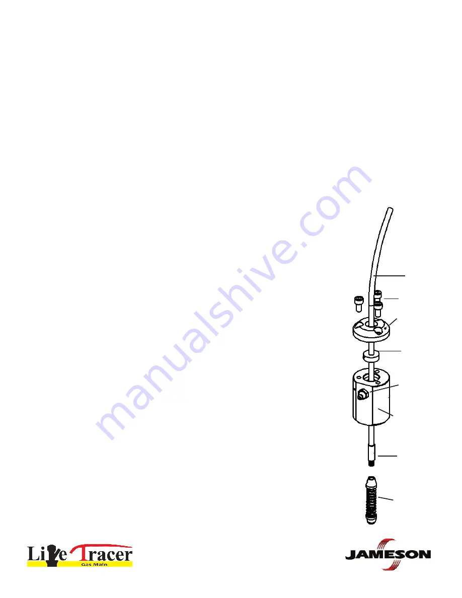
Rod
Stuffing
Box Cap
O-ring
1/4”
Grease
Fitting
Stuffing
Box Body
End
Ferrule
Spring
Leader
Accessory
Screws
Live Tracer Operation
Before Each Use:
Inspect O-ring
for any sign of tearing, cracking or pitting. Replace if damaged BEFORE EVERY USE. Jameson O-rings
are custom designed. Only Jameson-provided O-rings will guarantee proper safety and effectiveness.
Inspect rod
for damage. If rod surface is broken, replace rod. A scratched rod could cause leaking when scratch passes
through Stuffing Box O-ring. Portions of rod can be cut away and new end fitting attached if it is not necessary to replace
entire rod.
Follow your company safety procedures at all times. These instructions shall not take the precedence over any safety
procedures established by your company.
1. Access PE gas pipe to be traced. Install electrofusion Tap Tee to pipe. Follow all installation and safety procedures
provided with your equipment and those established by your company.
Install Rod into Stuffing Box
2. Remove cap of Stuffing Box by removing the 3 screws.
3. INSPECT O-RING. If it shows any sign of tearing, cracking or pitting, replace with
new O-ring.
4. Pay out rod approximately 15 feet.
5. Remove spring accessory then install rod end through Stuffing Box cap as shown.
6. Lubricate end ferrule, rod and inside O-ring with lubricated wipes provided. Install
O-ring over rod.
7. Insert rod end into Stuffing Box body.
8. Attach Spring Leader Accessory to end ferrule of rod.
9. Install Stuffing Box cap with 3 screws provided. Snugly secure all screws to
ensure proper O-ring seal.
10. Attach Stuffing Box to angled access port of Tap Tee. Follow your company’s
procedures for attaching to access port.
11. Open valve and check for gas leaks following your company procedures. If Stuffing
Box is leaking, inspect O-rings and rod for damage. Replace as necessary.
12. Mark rod with permanent marking pen 6” from Stuffing Box to monitor retracting
of rod.
800.346.1956
WWW.JAMESONLLC.COM


