


Page 3
1998-2006 Edition
1. The floor protection pad referred to throughout this manual must be safety listed, unless it is constructed
from a non-combustible material.
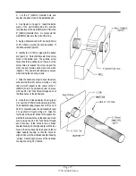
2. Outside air must be supplied for combustion. A 1-5/8" (41mm) minimum interior diameter metallic 0.16”
(4mm) thick wall air supply hose must be installed between the combustion air intake stub (located on the
back panel) and the outside of the home to provide outside combustion air. Failure to do so may cause
exhaust gases and soot particles to leak into the home under certain conditions. Any claims made for
damages caused by the use of interior room air for combustion will be voided.
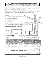
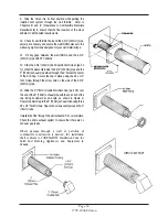
3. Any installation incorporating an existing chimney must include a re-lining of the existing chimney. All
existing chimneys must be relined using flexible galvanized or stainless steel vent pipe.
4. Installation of the J2001T Insert in a wood framed chase or other wood framed enclosure that does not
have an existing chimney system requires the use of rigid L-type pellet vent pipe. A minimum 3" (76mm)
clearance to combustible materials must be maintained from the outer surface of the L-type vent pipe used.
5. Galvanized or stainless steel flex vent pipe is required for installation of the J2001T Insert in
prefabricated wood-burning fireplaces with an existing chimney system.
6. Caution should be exercised when installing the J2001T in an old masonry fireplace. The flue tile may
be weak, broken or have large globs of mortar obstructing the exhaust flow. It is important to clean the
chimney and fireplace cavities thoroughly and completely before installing the insert. No short cuts should
be taken in cleaning the fireplace cavity before installing the fireplace insert. If the fireplace is not cleaned
property, the convection blower will pick up the existing soot and fly ash and blow it into the home causing
soot damage to the walls, draperies, carpeting and such.
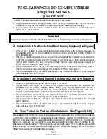
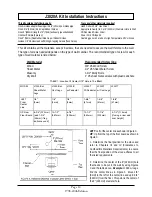
7. A 12" (305mm) minimum distance must be maintained at all times between the outlet of the exhaust rain
cap and the inlet opening of the air intake rain cap.
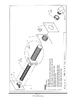
8. The required exhaust pipe diameter depends on the distance from the stove or insert to the termination
point of the vent pipe (chimney cap) and the number of elbows along the length of the vent system. As a
rule, if the total vent pipe length is 11 feet (3.4m) or more use 4" (102mm) diameter pipe. If the total length
is less than 11 feet (3.4m), use 3" (76mm) diameter pipe. If more than one 90 degree elbow is to be used,
increase the vent pipe diameter to 4" (102mm). No more than a total of 180 degrees of bends should be
used throughout the length of the vent system.
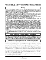
9. When assembling the chimney system, ensure that all pipe connections are sealed completely using
RTV high temperature silicone and high temperature foil tape. All connections, including twist-lock type
connections, must be sealed using RTV. If any of the connections are not sealed property, carbon monoxide
and ash will filter through these connections into the fireplace cavity, be picked up by the convection blower
and dispersed throughout the house. Any claims made for damages caused by improperly sealed vent pipe
joints will be voided.
10. Installation of a clean-out "T" at the first elbow of the vent pipe system, if possible, is recommended for
ease of cleaning and maintaining your chimney. Annual inspection and cleaning of the vent system is an
absolute requirement.
11. Use of "B" vent pipe (gas appliance vent pipe) with any Jamestown pellet stove or insert is strictly
prohibited.
General Requirements
II. INSTALLATION REQUIREMENTS
Summary of Contents for J1000B
Page 2: ......
Page 8: ...Page vi 1998 2006 Edition ...
Page 16: ...Page 8 1998 2006 Edition ...
Page 20: ...Page 12 1998 2006 Edition ...
Page 36: ...Page 28 1998 2006 Edition ...
Page 44: ...Page 36 1998 2006 Edition ...
Page 45: ...Page 37 1998 2006 Edition ...
Page 46: ...VIII 5 Jamestown Control Panel Page 38 1998 2006 Edition ...
Page 61: ...Page 53 1998 2006 Edition ...
Page 62: ...Page 54 1998 2006 Edition ...
Page 63: ...Page 55 1998 2006 Edition ...
Page 64: ...Page 56 1998 2006 Edition ...
Page 69: ...Page 61 1998 2006 Edition ...
Page 70: ...Page 62 1998 2006 Edition ...
Page 79: ...Appendix A 3 1998 2006 Edition ...
Page 80: ...Appendix A 4 1998 2006 Edition ...
Page 81: ...Appendix A 5 1998 2006 Edition ...
Page 82: ...Appendix A 6 1998 2006 Edition ...
Page 84: ...Appendix B 2 1998 2006 Edition ...
Page 87: ...APPENDIX E AUGER MOTOR BRACKET INSTALLATION Appendix E 1 1998 2006 Edition ...
Page 90: ...Appendix F 3 1998 2006 Edition ...
Page 93: ...APPENDIX H J1000 CROSSFLOW FAN Part 07EEG Appendix H 1 1998 2006 Edition ...
Page 94: ...APPENDIX I 1 EXHAUST BLOWER ASSEMBLY MODEL J1000 Appendix I 1 1998 2006 Edition ...