


Page 4
1998-2006 Edition
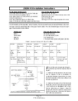
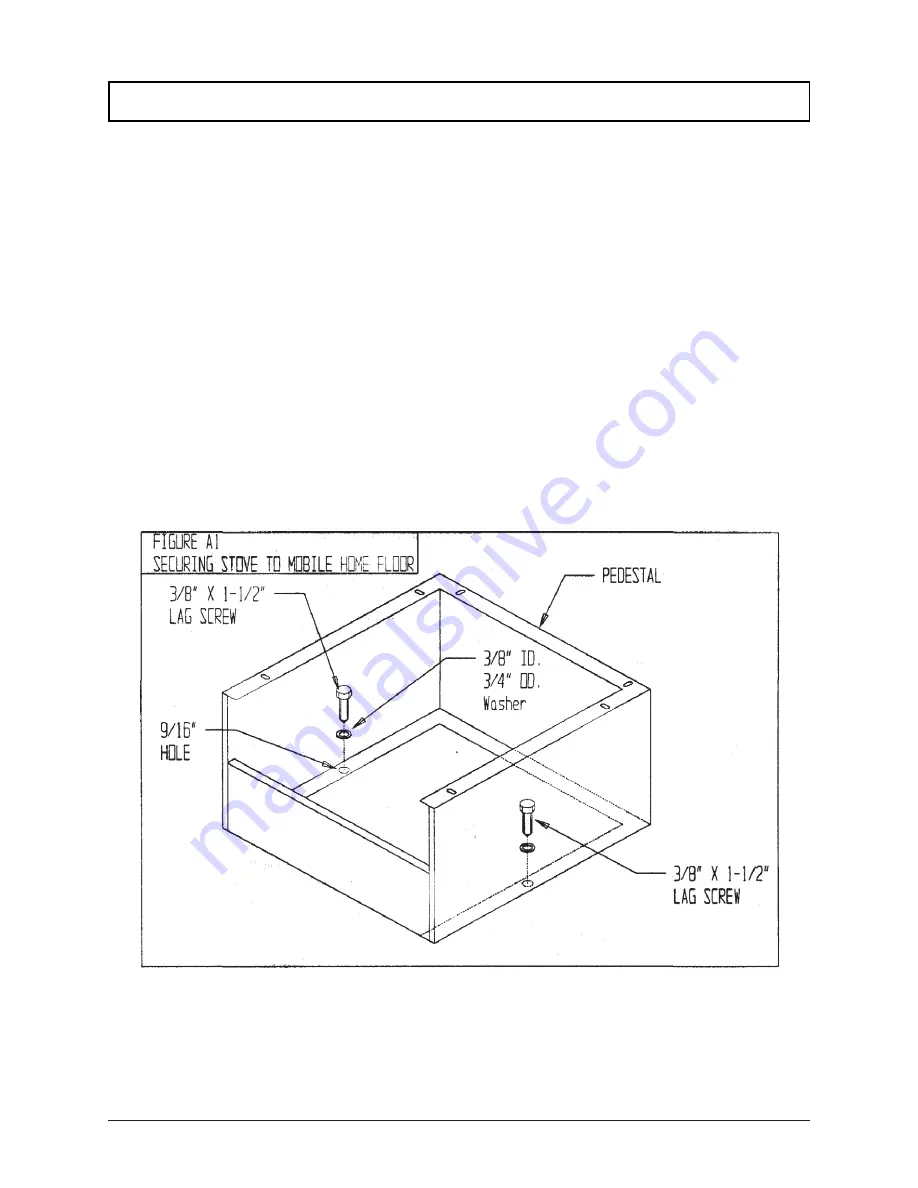
1. All manufactured home installations require the unit to be secured, permanently, to the floor or fireplace
hearth. See Figure A1, below. Units installed on top of sheet steel or cast iron legs will require an alternate
fastening method. A specific Jamestown Mobile Home Attachment kit is available through the local
Jamestown dealer. Please contact your local Jamestown dealer.
2. If installing in a manufactured home, the structural integrity of the manufactured home floor, wall, ceiling
and roof must be maintained.
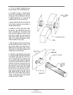
3. Outside air must be supplied for combustion. A 1-5/8" (41mm) minimum interior diameter air supply
hose must be installed between the combustion air intake stub (located on the back panel) and the outside
of the home to provide outside combustion air. Failure to do so may cause exhaust gases and soot particles
to leak into the home under certain conditions. Any claims made for damages caused by the use of interior
room air for combustion will be voided.
4. Do not install this unit in a sleeping room.
5. The appliance must be grounded in accordance with local codes or, in the absence of local codes, with
the current National Electrical Code ANSI/NFPA 70 in the USA or the current CSA C22.1 Canadian Electrical
Code. Use copper lugs to mechanically fasten a #8 grounding wire to the stove body or pedestal and the
steel frame of the manufactured home. Should you have questions, please consult the local building code
enforcing official in your area.
Manufactured (Mobile) Home Installation Requirements
SECURE TO FLOOR
Must meet requirements under UL1482 Section 52.2.3 e.
Summary of Contents for J1000B
Page 2: ......
Page 8: ...Page vi 1998 2006 Edition ...
Page 16: ...Page 8 1998 2006 Edition ...
Page 20: ...Page 12 1998 2006 Edition ...
Page 36: ...Page 28 1998 2006 Edition ...
Page 44: ...Page 36 1998 2006 Edition ...
Page 45: ...Page 37 1998 2006 Edition ...
Page 46: ...VIII 5 Jamestown Control Panel Page 38 1998 2006 Edition ...
Page 61: ...Page 53 1998 2006 Edition ...
Page 62: ...Page 54 1998 2006 Edition ...
Page 63: ...Page 55 1998 2006 Edition ...
Page 64: ...Page 56 1998 2006 Edition ...
Page 69: ...Page 61 1998 2006 Edition ...
Page 70: ...Page 62 1998 2006 Edition ...
Page 79: ...Appendix A 3 1998 2006 Edition ...
Page 80: ...Appendix A 4 1998 2006 Edition ...
Page 81: ...Appendix A 5 1998 2006 Edition ...
Page 82: ...Appendix A 6 1998 2006 Edition ...
Page 84: ...Appendix B 2 1998 2006 Edition ...
Page 87: ...APPENDIX E AUGER MOTOR BRACKET INSTALLATION Appendix E 1 1998 2006 Edition ...
Page 90: ...Appendix F 3 1998 2006 Edition ...
Page 93: ...APPENDIX H J1000 CROSSFLOW FAN Part 07EEG Appendix H 1 1998 2006 Edition ...
Page 94: ...APPENDIX I 1 EXHAUST BLOWER ASSEMBLY MODEL J1000 Appendix I 1 1998 2006 Edition ...


