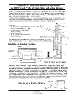


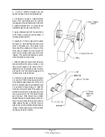

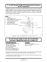

A. Installation In A Pre-Manufactured Wood Burning Fireplace (See Figure 6)
B. Installation In A Wood Framed Enclosure/Chase (See Figure 6)
IV. CLEARANCES TO COMBUSTIBLES
REQUIREMENTS
J2001T INSERT
Page 9
1998-2006 Edition
The J2001T fireplace insert can be installed inside two types of enclosures:
A. A pre-manufactured wood burning fireplace, either masonry or sheet metal, that has not been
modified in any way that may reduce the original fire protection capability of that fireplace.
B. A wood framed enclosure such as a chase or other form of wooden enclosure with the appropriate
clearances as specified below.
1. If this Insert is installed in a pre-manufactured wood burning fireplace, the minimum clearances to
combustibles affect only the portion of this Insert which protrudes into the room from the front face of
the existing fireplace.
2. This type of installation must include an approved non-combustible floor protection pad equivalent to
a 3/8" (9.5mm) millboard (Backer Board™) minimum or a masonry hearth which extends a minimum
of 6" (152mm) from the front face of the Insert (where the door gasket touches when closed) and
5" (127mm) from either side. See Figure 6.
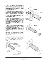
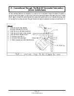
3. The minimum distance from the top of the Insert (trivet surface) to the bottom of a mantel, shelf, or
other combustible overhang extending over this unit is 18" (457mm). See Figure 7.
4. The minimum distance from this insert's side panels to any combustible material or surface adjacent
to the side panel must be 3" (76mm).
1. Minimum clearances to combustibles affects all parts of this Insert.
2. The installation must include, as a minimum, an approved non-combustible floor protection pad
equivalent to a 3/8" (9.5mm) millboard (Backer Board™) or a masonry hearth which extends a
minimum of 6" (152mm) from the front face of the Insert (where the door gasket touches when
closed), 5" (127mm) from either side and 1" (25mm) from the back panel. See Figure 5.
3. The minimum distance from the top of the Insert (trivet surface) to the bottom of a mantel, shelf, or
other combustible overhang extending over this unit is 18” (457mm).
4. The minimum distance from the fuel hopper top to the ceiling inside the wood framed enclosure must
be 36" (914mm).
5. The minimum distance from this insert's side panels to any combustible material or surface adjacent
to the side panel must be 5" (127mm).
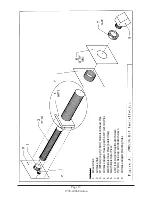
C. Floor Protection Pad for all Installations (See Figure 5 & 6)
All installations of the J2001T Insert must include an approved non-combustible floor protection pad equivalent to
a 3/8" (9.5mm) millboard minimum or a masonry hearth which extends a minimum of 6" (152mm) from the front
face of the Insert (where the door gasket touches when closed) and 5" (127mm) from either side. If installing this
Insert on a combustible floor (constructed of wood framing, wafer board, particle board or the like) the floor
protection pad must also extend 1" (25mm) beyond the back panel of the stove. The floor protection pad selected
(unless installing on a masonry hearth) must be safety approved. Consult local building or fire code enforcement
officials before selecting the floor protection pad material.
Important
Install in accordance with CAN/CSA-B365 Installation Code for Solid Burning Appliances and Equipment.
Summary of Contents for J1000B
Page 2: ......
Page 8: ...Page vi 1998 2006 Edition ...
Page 16: ...Page 8 1998 2006 Edition ...
Page 20: ...Page 12 1998 2006 Edition ...
Page 36: ...Page 28 1998 2006 Edition ...
Page 44: ...Page 36 1998 2006 Edition ...
Page 45: ...Page 37 1998 2006 Edition ...
Page 46: ...VIII 5 Jamestown Control Panel Page 38 1998 2006 Edition ...
Page 61: ...Page 53 1998 2006 Edition ...
Page 62: ...Page 54 1998 2006 Edition ...
Page 63: ...Page 55 1998 2006 Edition ...
Page 64: ...Page 56 1998 2006 Edition ...
Page 69: ...Page 61 1998 2006 Edition ...
Page 70: ...Page 62 1998 2006 Edition ...
Page 79: ...Appendix A 3 1998 2006 Edition ...
Page 80: ...Appendix A 4 1998 2006 Edition ...
Page 81: ...Appendix A 5 1998 2006 Edition ...
Page 82: ...Appendix A 6 1998 2006 Edition ...
Page 84: ...Appendix B 2 1998 2006 Edition ...
Page 87: ...APPENDIX E AUGER MOTOR BRACKET INSTALLATION Appendix E 1 1998 2006 Edition ...
Page 90: ...Appendix F 3 1998 2006 Edition ...
Page 93: ...APPENDIX H J1000 CROSSFLOW FAN Part 07EEG Appendix H 1 1998 2006 Edition ...
Page 94: ...APPENDIX I 1 EXHAUST BLOWER ASSEMBLY MODEL J1000 Appendix I 1 1998 2006 Edition ...