


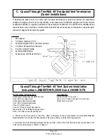
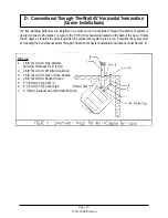
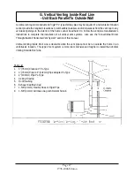

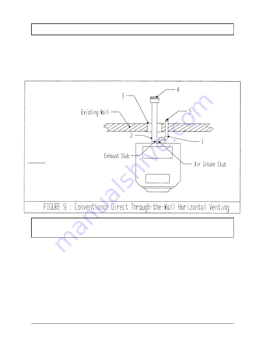
B. Conventional Direct Through-The-Wall Horizontal Vent Termination
Conventional Direct Through-The-Wall Horizontal Vent
System Installation Instructions
Page 18
1998-2006 Edition
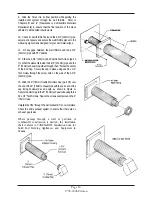
A conventional direct vent system must be constructed from a 3" (76mm) diameter listed "PL" type pipe and
1-5/8" (41mm) diameter rigid or flexible hose or pipe. The 3" (76mm) diameter "L" type pipe transports the
exhaust gases while the 1-5/8" (41mm) diameter hose or pipe transports combustion air from the outside of
the home to the stove. This type of vent system is easy to install and maintain. However, two holes must be
cut in the exterior wall for this system to pass through. All components required for this vent system are
available at all local hardware stores and at the local Jamestown Dealer.
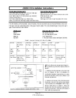
It is necessary to cut a 7" (178mm) and a 1-3/4" (45mm) diameter hole in the wall as passages for the vent pipe and the air
intake tube.
1. Determine the location of the 7" (178mm) diameter hole by referring to the section labeled "J3020A kit Installation
Instructions" in this manual. Mark the hole location.
2. Determine the location of the 1-3/4" (45mm) hole. Determine this location based on the tube material that you are
using. Remember that the openings in the exhaust vent cap must be a minimum of 12" (305mm) from the openings
in the air intake rodent screen openings.
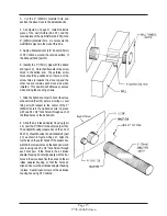
3. Cut the 7" and the 1-3/4" (178mm and 45mm) holes in the wall using an appropriate saw.
4. Move the stove away from the wall to provide enough clearance for the entire length of the exhaust pipe.
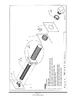
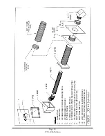
Parts List
1.
1-5/8” (41mm) Diameter Hose or Pipe
2.
3” (76mm) PL-Type Vent Pipe
3.
3” (76mm) Wall Thimble
4.
3” (76mm) Exhaust Cap with Rodent Screen
5.
1-5/8” (41mm) Air Intake Rodent Screen
Summary of Contents for J1000B
Page 2: ......
Page 8: ...Page vi 1998 2006 Edition ...
Page 16: ...Page 8 1998 2006 Edition ...
Page 20: ...Page 12 1998 2006 Edition ...
Page 36: ...Page 28 1998 2006 Edition ...
Page 44: ...Page 36 1998 2006 Edition ...
Page 45: ...Page 37 1998 2006 Edition ...
Page 46: ...VIII 5 Jamestown Control Panel Page 38 1998 2006 Edition ...
Page 61: ...Page 53 1998 2006 Edition ...
Page 62: ...Page 54 1998 2006 Edition ...
Page 63: ...Page 55 1998 2006 Edition ...
Page 64: ...Page 56 1998 2006 Edition ...
Page 69: ...Page 61 1998 2006 Edition ...
Page 70: ...Page 62 1998 2006 Edition ...
Page 79: ...Appendix A 3 1998 2006 Edition ...
Page 80: ...Appendix A 4 1998 2006 Edition ...
Page 81: ...Appendix A 5 1998 2006 Edition ...
Page 82: ...Appendix A 6 1998 2006 Edition ...
Page 84: ...Appendix B 2 1998 2006 Edition ...
Page 87: ...APPENDIX E AUGER MOTOR BRACKET INSTALLATION Appendix E 1 1998 2006 Edition ...
Page 90: ...Appendix F 3 1998 2006 Edition ...
Page 93: ...APPENDIX H J1000 CROSSFLOW FAN Part 07EEG Appendix H 1 1998 2006 Edition ...
Page 94: ...APPENDIX I 1 EXHAUST BLOWER ASSEMBLY MODEL J1000 Appendix I 1 1998 2006 Edition ...