


Page 21
1998-2006 Edition
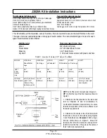
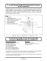
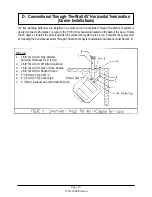
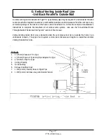
3. Determine the horizontal location of the center of the 9" (229mm) hole by moving the stove to its final position,
attaching the 3" (76mm) 45 degree elbow and the 3" (76mm) exhaust pipe with belled end to the exhaust stub of the
stove. Mark the hole location on the wall.
4. Cut the 9" (229mm) diameter hole and position the stove close to the installation site. Remember to maintain all
the required clearances to the walls and any combustible objects adjacent to the stove. Refer to Chapter III and IV of
this manual.
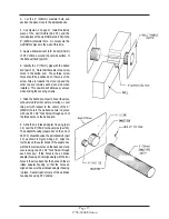
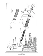
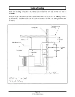
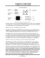
5. See Figure B. Apply a liberal amount of RTV silicone around the perimeter of the non-belled end of the 45 degree
3" (76mm) elbow (part # 6). Slide the belled end of the 3" (76mm) exhaust pipe (Part # 7) over the non-belled end of
the 45 degree 3" (76mm) elbow ( Part # 6) and secure together using three (3) #8 Teck Screws spaced equally around
the perimeter.
6. Apply a liberal amount of RTV silicone to the outside surface of the Exhaust Stub (part #1). Install the exhaust pipe
and 45 degree elbow assembly onto the stove exhaust stub by sliding the belled end of the 45 degree elbow (Part # 6)
over the stove exhaust stub (Part #1) as far as it will go. Orient the 3" (76mm) exhaust pipe properly with respect to the
9" (229mm) hole in the wall. Secure this assembly to the exhaust stub using three (3) #8 Teck Screws spaced equally
around the perimeter. The attached assembly must be in a horizontal position and parallel to the floor.
7. Determine the total length of 3" (76mm) exhaust pipe required to exit the wall. The exhaust termination cap must be
12 inches (305mm) away from the outside surface of the wall. If an additional 3" (76mm) exhaust pipe extension (Part
# 7) is required to reach this length, cut the extra part # 7 to the required length using a hacksaw and attach to the 3"
(76mm) exhaust pipe, already attached to the 45 degree elbow, after first applying a bead of RTV silicone to the non-
belled end of the 3" (76mm) exhaust pipe that is already attached to the stove. Note: If the second 3" (76mm) exhaust
pipe is required, an extra 4-3/4" (121mm) air intake pipe extension is also required. Cut the 4-3/4" (121mm) extension
pipe (supplied with the J3030A and J3030B kits) to the same length as the second 3" (76mm) exhaust pipe. Do not
attach this 4-3/4" (121mm) extension pipe at this time.
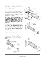
8. FOR MODELS J1000B AND J2000T USING THE J3030B KIT: Slide the air intake adapter extension (part # 4) over
the 3" (76mm) pipe assembly attached to the stove. Align the open slots in the 45 degree housing extension with the
mounting holes (#3). Secure the air intake adapter extension to the back panel using #8 x 1/2" Teck screws. For Model
J3000A, the air intake adapter extension (part #4) is not required and is not shipped with J3030A kit.
9. Note that the 45 degree elbow housing is not a symmetrical part. It must be oriented as shown in the diagram
below to provide enough room for the 45 degree 3" (76mm) elbow. Align the open slots in Part #4 with the open slots
in Part # 5. If this position does not provide enough room for the 45 degree 3" (76mm) elbow to fit inside part #5,
remove part #5 and rotate to align the open slots on the opposite with the open slots on part #4. Slide the 45 degree
elbow housing (Part # 5) over the 3" (76mm) pipe assembly. Make sure that Part # 5 is oriented property towards the
direction of the 9" (229mm) hole in the wall.
10. Align the open slots in the outward bends of air intake adapter housing (part #8) with the open slots in the 45
degree elbow housing (Part # 5) as shown in Figure B. Secure these two parts together using a #8 x 1/2" Phillips
machine screws and nuts.
11. Place the inside and outside pieces of the wall thimble (Part #6 and #7) into the 9" (229mm) diameter hole. Do
not secure the wall thimble pieces to the wall at this time.
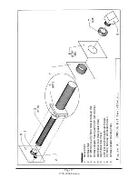
12. Connect the 4-3/4" (121mm) air intake pipe extension to the end of the 4-3/4" (121mm) air intake pipe that is
attached to part #8 using the 4-3/4" (121mm) coupling provided with the J3030A and J3030B kits. Secure these parts
together by driving three (3) #8 x 1/2" Teck Screws through each pipe and coupling connection. Space these screws
evenly around the perimeter of the pipe. Note: The Teck Screw heads protruding from the surface of the 4-3/4"
(121mm) coupler may prevent this assembly from sliding through the hole in the wall thimble. You may want to use
the Teck Screws after sliding the assembly through the wall first.
Summary of Contents for J1000B
Page 2: ......
Page 8: ...Page vi 1998 2006 Edition ...
Page 16: ...Page 8 1998 2006 Edition ...
Page 20: ...Page 12 1998 2006 Edition ...
Page 36: ...Page 28 1998 2006 Edition ...
Page 44: ...Page 36 1998 2006 Edition ...
Page 45: ...Page 37 1998 2006 Edition ...
Page 46: ...VIII 5 Jamestown Control Panel Page 38 1998 2006 Edition ...
Page 61: ...Page 53 1998 2006 Edition ...
Page 62: ...Page 54 1998 2006 Edition ...
Page 63: ...Page 55 1998 2006 Edition ...
Page 64: ...Page 56 1998 2006 Edition ...
Page 69: ...Page 61 1998 2006 Edition ...
Page 70: ...Page 62 1998 2006 Edition ...
Page 79: ...Appendix A 3 1998 2006 Edition ...
Page 80: ...Appendix A 4 1998 2006 Edition ...
Page 81: ...Appendix A 5 1998 2006 Edition ...
Page 82: ...Appendix A 6 1998 2006 Edition ...
Page 84: ...Appendix B 2 1998 2006 Edition ...
Page 87: ...APPENDIX E AUGER MOTOR BRACKET INSTALLATION Appendix E 1 1998 2006 Edition ...
Page 90: ...Appendix F 3 1998 2006 Edition ...
Page 93: ...APPENDIX H J1000 CROSSFLOW FAN Part 07EEG Appendix H 1 1998 2006 Edition ...
Page 94: ...APPENDIX I 1 EXHAUST BLOWER ASSEMBLY MODEL J1000 Appendix I 1 1998 2006 Edition ...