


Page 22
1998-2006 Edition
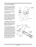
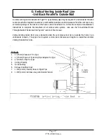
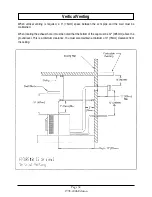
13. Slide the Stove into its final position while guiding the installed vent system through the wall thimble. Refer to
Chapters III and IV (Clearances to Combustible Materials Requirements) to ensure that the final position of the stove
adheres to all the listed clearance requirements.
14. Check for wall thimble fit around the 4-3/4" (121mm) pipe, adjust as necessary and secure the wall thimble pieces
to the wall using eight screws designed for your wall material type.
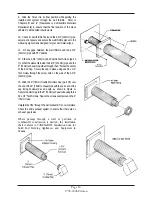
15. Fill any gaps between the wall thimble and the 4-3/4" (121mm) pipe with RTV silicone.
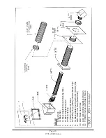
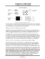
16. Slide the 4-3/4" (121mm) End Cap/Rodent Screen (part# 11) so that the sleeve fits inside the end of the 4-3/4"
(121mm) pipe extension and the 3" (76mm) exhaust pipe slides through the 3" (76mm) hole at the center of the End
Cap. Secure the cap in place using one #8 x 1/2" Teck Screw through the side of the 4-3/4" (121mm) pipe.
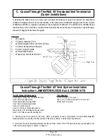
17. Slide the 3" (76mm) Double Wall Rain Cap (part # 9) over the end of the 3" (76mm) exhaust pipe with the open
end of the cap facing downward at an angle, as shown in Figure B. Secure the Rain Cap to the 3" (76mm) exhaust
tube using three #8 x 1/2" Teck Screws. Space the screws evenly around the 3" (76mm) tube.
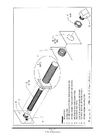
Installation of the Coaxial Through-The-Wall 45 Degree Vent System is now complete. Check the entire exhaust
system to ensure that there are no exhaust gas leaks.
Summary of Contents for J1000B
Page 2: ......
Page 8: ...Page vi 1998 2006 Edition ...
Page 16: ...Page 8 1998 2006 Edition ...
Page 20: ...Page 12 1998 2006 Edition ...
Page 36: ...Page 28 1998 2006 Edition ...
Page 44: ...Page 36 1998 2006 Edition ...
Page 45: ...Page 37 1998 2006 Edition ...
Page 46: ...VIII 5 Jamestown Control Panel Page 38 1998 2006 Edition ...
Page 61: ...Page 53 1998 2006 Edition ...
Page 62: ...Page 54 1998 2006 Edition ...
Page 63: ...Page 55 1998 2006 Edition ...
Page 64: ...Page 56 1998 2006 Edition ...
Page 69: ...Page 61 1998 2006 Edition ...
Page 70: ...Page 62 1998 2006 Edition ...
Page 79: ...Appendix A 3 1998 2006 Edition ...
Page 80: ...Appendix A 4 1998 2006 Edition ...
Page 81: ...Appendix A 5 1998 2006 Edition ...
Page 82: ...Appendix A 6 1998 2006 Edition ...
Page 84: ...Appendix B 2 1998 2006 Edition ...
Page 87: ...APPENDIX E AUGER MOTOR BRACKET INSTALLATION Appendix E 1 1998 2006 Edition ...
Page 90: ...Appendix F 3 1998 2006 Edition ...
Page 93: ...APPENDIX H J1000 CROSSFLOW FAN Part 07EEG Appendix H 1 1998 2006 Edition ...
Page 94: ...APPENDIX I 1 EXHAUST BLOWER ASSEMBLY MODEL J1000 Appendix I 1 1998 2006 Edition ...