

VIII.1 Introduction to Efficiencies
VIII.2 Achieving An Efficient Burn
VIII. OPERATING INSTRUCTIONS FOR
ALL MODELS EQUIPPED WITH THE
SC300T CONTROL BOARD
Page 33
1998-2006 Edition
Warning
Read this entire section thoroughly before attempting to operate your new stove. If you fail to understand some
of the operational procedures or operating characteristics, contact your local Jamestown Dealer for further
detailed explanations. Failure to heed this warning can result in serious stove component(s) damage that is not
covered under the Jamestown Warranty.
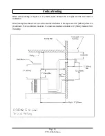
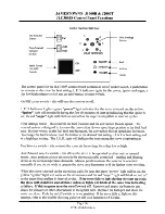
Pellets are delivered to the firepot by an auger/gravity feed system. The pellet fuel feed rate is controlled by
the Fuel Feed Control Knob and/or a wall thermostat. The burn rate of the pellets in the firepot is controlled
by the amount of combustion air entering the firepot, which is controlled by the Draft Control Knob. As the
pellets are burned, the hot exhaust gases are drawn past the exterior surfaces of the heat exchanger tubes
and through the side heat exchanger chambers, then blown into the vent pipe system. Cool room air is
blown by the convection blower through the heat exchanger tubes and past the exterior surfaces of the side
heat exchanger chambers. The room air absorbs heat from the hot metal surfaces and flows into the room.
The overall efficiency of the stove is determined by two factors:
1. How efficiently the pellets are burning. This is called the combustion efficiency.
2. How much room air is blowing past the heat exchanger surfaces and extracting heat from the metal
surfaces. This is called the heat transfer efficiency.
In order to achieve the maximum overall efficiency, both the combustion efficiency and the heat transfer
efficiency have to be at their maximum levels. This stove design automatically maximizes the heat transfer
efficiency by combining the fuel feed rate and the convection blower speed into one control knob. As the
fuel feed rate is increased, the convection blower speed will also increase. However; you, as the consumer,
will have to learn to maximize the combustion efficiency.
Learning to properly regulate the combustion air (draft) flow rate according to the pellet fuel feed rate is the
key to maximizing the combustion efficiency and, consequently, the fuel consumption rate and the heating
capacity of the stove. Spend a few minutes watching the instructional video and reading this manual before
attempting to burn your new stove. Pay particular attention to the sections labeled Achieving an Efficient
Burn and Efficient Flame Characteristics . If you have further questions, contact your Jamestown Dealer.
Being able to burn the stove efficiently requires a proper balance between the fuel feed rate and the
combustion air/draft rate. A proper air to fuel ratio can only be established once the fire is burning steadily
and is self-sustaining. The "proper" setting is when the optimum air to fuel ratio is obtained.
All manufacturers must provide a unit which is capable of burning at sea level and also at 11,000 feet
(3353m) above sea level. Furthermore, the same unit must be able to burn fuels of variable size and quality.
At sea level, while burning 1/4" (6.35mm) diameter pellets on the #1 fuel feed setting, enough oxygen is
available to burn efficiently at (or very near) the lowest draft setting. At 11,000 (3353m) feet above sea level,
however, there simply isn't enough oxygen available in the air to burn any diameter pellet fuel at the lowest
draft setting and the lowest fuel feed setting.
Summary of Contents for J1000B
Page 2: ......
Page 8: ...Page vi 1998 2006 Edition ...
Page 16: ...Page 8 1998 2006 Edition ...
Page 20: ...Page 12 1998 2006 Edition ...
Page 36: ...Page 28 1998 2006 Edition ...
Page 44: ...Page 36 1998 2006 Edition ...
Page 45: ...Page 37 1998 2006 Edition ...
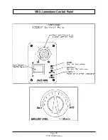
Page 46: ...VIII 5 Jamestown Control Panel Page 38 1998 2006 Edition ...
Page 61: ...Page 53 1998 2006 Edition ...
Page 62: ...Page 54 1998 2006 Edition ...
Page 63: ...Page 55 1998 2006 Edition ...
Page 64: ...Page 56 1998 2006 Edition ...
Page 69: ...Page 61 1998 2006 Edition ...
Page 70: ...Page 62 1998 2006 Edition ...
Page 79: ...Appendix A 3 1998 2006 Edition ...
Page 80: ...Appendix A 4 1998 2006 Edition ...
Page 81: ...Appendix A 5 1998 2006 Edition ...
Page 82: ...Appendix A 6 1998 2006 Edition ...
Page 84: ...Appendix B 2 1998 2006 Edition ...
Page 87: ...APPENDIX E AUGER MOTOR BRACKET INSTALLATION Appendix E 1 1998 2006 Edition ...
Page 90: ...Appendix F 3 1998 2006 Edition ...
Page 93: ...APPENDIX H J1000 CROSSFLOW FAN Part 07EEG Appendix H 1 1998 2006 Edition ...
Page 94: ...APPENDIX I 1 EXHAUST BLOWER ASSEMBLY MODEL J1000 Appendix I 1 1998 2006 Edition ...


