


VIII.6 Introduction To The Control Panel
Page 39
1998-2006 Edition
Location of Controls
On freestanding stoves (models J1000B, J2000T) the control switches are located on the right side panel.
On the fireplace insert (model J2001T) the control switches are located on the right shroud leg. On all model
stoves, the Manual Draft Control is located below the Fuel Feed Knob control panel.
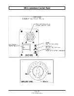
ON/OFF Switch
On the right shroud leg of the insert and the right side panel of the stove are the operating switch and knob.
The rocker switch is the Main Power On/Off Switch. This switch controls the electrical power to the entire
stove. Your stove won't start if this switch is in the "OFF" position. Push this switch to the "ON" position. You
should hear the exhaust blower motor turn on.
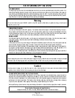
WARNING: Never turn the Power On/Off switch to the OFF position during the startup cycle if the pellets in
the firepot have ignited. Doing so can cause smoke to billow out.
Please note that if the stove is hot, turning this switch to the "OFF" position will not turn off the exhaust
blower. It will, however, turn off the fuel feed and lower the convection blower speed to the lowest setting.
The exhaust blower will continue to operate until the unit has cooled.
WARNING: Never connect the power supply cord of this unit to an electrical outlet controlled by a wall
switch. Never disconnect the power supply cord to turn this unit off. Always use the ON/OFF Switch that is
installed in the stove.
Fuel Feed Control Knob
Above the On/Off Switch is a silver faced rotary control knob. This control knob has a black pointer arrow
that points at numbers ranging from 1 to 6, when turned. Although numbered 1 through 6, this knob can be
turned incrementally to 20 positions between the numbers 1 and 6. This knob controls the fuel feed rate and
the convection blower speed. #1 is the lowest setting for both fuel feed rate and convection blower speed
and #6 is the highest setting. This control system is designed to increase the convection blower speed in
proportion to the fuel feed rate. In other words, as the fuel feed rate increases, the convection blower speed
also increases. This controlled balance maximizes the efficiency of your stove and also prevents it from
overheating.
NOTE: The Fuel Feed Control Knob will have no effect on the fuel feed rate or the convection blower speed
until the stove has warmed up sufficiently.
Freestanding Stove Draft Control Knob
On the J1000B and J2000T stoves, the Draft Control Knob is located below the main control panel. Around
this knob are numbers ranging from 1 to 6. Note that the knob can be turned in either direction; clock-wise
or counter-clockwise. Setting the knob to 1 provides the least amount of combustion air and setting the knob
to 6 provides the greatest amount of combustion air. See the following paragraph "J2001 Draft Control Knob"
for draft control procedures.
Model J2001T Draft Control Knob
Within the fifth louver opening from the bottom of the right side panel is a round black knob. This is the Draft
or Combustion Air Control Knob. This knob is adjustable from 1 to 6. Setting 1 provides the least amount
of combustion air and setting 6 provides the highest amount of combustion air. To adjust the draft control,
turn this knob counter clockwise 1/4 turn then slide to the desired position. Turn this knob clockwise 1/4 turn
to lock it at the desired position.
Summary of Contents for J1000B
Page 2: ......
Page 8: ...Page vi 1998 2006 Edition ...
Page 16: ...Page 8 1998 2006 Edition ...
Page 20: ...Page 12 1998 2006 Edition ...
Page 36: ...Page 28 1998 2006 Edition ...
Page 44: ...Page 36 1998 2006 Edition ...
Page 45: ...Page 37 1998 2006 Edition ...
Page 46: ...VIII 5 Jamestown Control Panel Page 38 1998 2006 Edition ...
Page 61: ...Page 53 1998 2006 Edition ...
Page 62: ...Page 54 1998 2006 Edition ...
Page 63: ...Page 55 1998 2006 Edition ...
Page 64: ...Page 56 1998 2006 Edition ...
Page 69: ...Page 61 1998 2006 Edition ...
Page 70: ...Page 62 1998 2006 Edition ...
Page 79: ...Appendix A 3 1998 2006 Edition ...
Page 80: ...Appendix A 4 1998 2006 Edition ...
Page 81: ...Appendix A 5 1998 2006 Edition ...
Page 82: ...Appendix A 6 1998 2006 Edition ...
Page 84: ...Appendix B 2 1998 2006 Edition ...
Page 87: ...APPENDIX E AUGER MOTOR BRACKET INSTALLATION Appendix E 1 1998 2006 Edition ...
Page 90: ...Appendix F 3 1998 2006 Edition ...
Page 93: ...APPENDIX H J1000 CROSSFLOW FAN Part 07EEG Appendix H 1 1998 2006 Edition ...
Page 94: ...APPENDIX I 1 EXHAUST BLOWER ASSEMBLY MODEL J1000 Appendix I 1 1998 2006 Edition ...


